
Specifications


2-9
Catalyst 6500 Series Switch and Cisco 7600 Series Router Network Analysis Module Installation and Configuration Note
78-16413-01
Chapter 2 Installing the Network Analysis Module
Installing and Removing the NAM
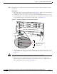
Figure 2-3 Ejector Lever Closure in a Horizontal Slot Chassis
Note Failure to fully seat the module in the backplane connector can result in error messages.
e. Tighten the two captive installation screws on the supervisor engine or module.
Note Make sure that the ejector levers are fully closed before tightening the captive installation
screws.
Vertical slots
a. Position the supervisor engine or switching module in the slot. (See Figure 2-4.) Make sure that you
align the sides of the switching module carrier with the slot guides on the top and bottom of the slot.
1
2
3
F
A
N
S
T
A
T
U
S
4
5
6
S
U
P
E
R
V
IS
O
R
2
W
S
-X
6
K
-S
U
P
2
-2
G
E
STATUS
SYSTEM
CONSOLE
PW
R MGMT
RESET
C
O
N
S
O
L
E
C
O
N
S
O
L
E
P
O
R
T
M
O
D
E
P
C
M
C
I
A
E
J
E
C
T
P
O
R
T
1
P
O
R
T
2
S
w
i
tc
h
L
o
a
d
1
0
0
%
1
%
L
I
N
K
L
I
N
K
SU
P
E
R
V
IS
O
R
2
W
S
-X
6
K-S
U
P
2-2G
E
STATUS
SYSTEM
CONSOLE
PWR MGMT
RESET
C
O
N
S
O
L
E
C
O
N
S
O
L
E
P
O
R
T
M
O
D
E
P
C
M
C
I
A
E
J
E
C
T
P
O
R
T
1
P
O
R
T
2
S
w
it
c
h
L
o
a
d
1
0
0
%
1
%
L
I
N
K
L
I
N
K
S
W
IT
C
H
F
A
B
R
IC
M
D
L
W
S-C6500-SFM
S
T
A
T
U
S
A
C
T
IV
E
S
E
L
E
C
T
N
E
X
T
58571
Ejector levers flush
with module faceplate