
Specifications


2-6
Catalyst 6500 Series Switch and Cisco 7600 Series Router Network Analysis Module Installation and Configuration Note
78-16413-01
Chapter 2 Installing the Network Analysis Module
Installing and Removing the NAM
To install a supervisor engine or module in the chassis, perform these steps:
Step 1 Choose a slot for the supervisor engine or module.
Step 2 Verify that there is enough clearance to accommodate any interface equipment that you will connect
directly to the supervisor engine or module ports. If possible, place modules between empty slots that
contain only module filler plates.
Step 3 Verify that the captive installation screws are tightened on all modules installed in the chassis.
This action ensures that the EMI gaskets on all modules are fully compressed in order to maximize the
opening space for the new module or the replacement module.
Note If the captive installation screws are loose, the EMI gaskets on the installed modules will push
adjacent modules toward the open slot, reducing the opening size and making it difficult to
install the replacement module.
Step 4 Remove the module filler plate by removing the two Phillips pan-head screws from the filler plate.
To remove a module, refer to the “Removing a Module” section on page 2-4.
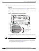
Step 5 Fully open both ejector levers on the new or replacement module. (See Figure 2-1.)