
Specifications


White Paper
© 2009 Cisco Systems, Inc. All rights reserved. This document is Cisco Public Information. Page 38 of 89
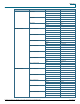
Figure 26. Receive Drop Thresholds—Example uses 1P1Q4T threshold (on GE ports)
As shown in the above diagram, frames arrive and are placed in the queue. As the queue starts to fill, the thresholds
are monitored by the port ASIC. When a threshold is breached, frames with CoS values identified by the
administrator are dropped randomly from the queue. The default threshold mappings for the different queue
structures are shown below.
Table 17. Per Queue Structure Default Threshold Mappings
Feature Default Value
CoS 0, 1, 2, 3, 4
Tail Drop 80%
Threshold 1
WRED Not Supported
CoS 5, 6, 7
Tail Drop 100%
1Q2T Receive Queue
Threshold 2
WRED Not Supported
CoS 0, 1
Tail Drop 50%
Threshold 1
WRED Not Supported
CoS 2,3
Tail Drop 60%
Threshold 2
WRED Not Supported
CoS 4,5
Tail Drop 80%
Threshold 3
WRED Not Supported
CoS 6,7
Tail Drop 100%
1Q4T Receive Queue
Threshold 4
WRED Not Supported
CoS 0, 1
Tail Drop 50%
Threshold 1
WRED Not Supported
CoS 2,3
Tail Drop 60%
Threshold 2
WRED Not Supported
CoS 4
Tail Drop 80%
Threshold 3
WRED Not Supported
CoS 6,7
1P1Q4T Receive Queue
Threshold 4
Tail Drop 100%