
Specifications

15
Installation and Configuration Note for the Catalyst 4500 Series Supervisor Engine II-Plus TS
78-16551-01
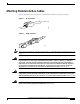
Attaching Module Interface Cables
Attaching Module Interface Cables
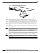
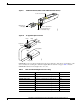
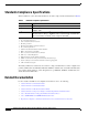
Figure 4 shows the connector types used to attach interface cables to the supervisor engine.
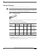
Figure 4 RJ-45 Connector
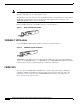
Figure 5 MT-RJ Connector
Note Always keep caps and plugs on the fiber-optic connectors on the cable and the switch when they are not
in use.
Warning
Voltages that present a shock hazard may exist on Power over Ethernet (PoE) circuits if
interconnections are made using uninsulated exposed metal contacts, conductors, or terminals.
Avoid using such interconnection methods, unless the exposed metal parts are located within a
restricted access location and users and service people who are authorized within the restricted
access location are made aware of the hazard. A restricted access area can be accessed only
through the use of a special tool, lock and key or other means of security. Statement 1072
Warning
Toavoidelectricshock,donotconnect safety extra-low voltage (SELV) circuits to telephone-network
voltage (TNV) circuits. LAN ports contain SELV circuits, and WAN ports contain TNV circuits. Some
LAN and WAN ports both use RJ-45 connectors. Use caution when connecting cables. Statement 1021
Warning
Invisible laser radiation may be emitted from disconnected fibers or connectors. Do not stare into
beams or view directly with optical instruments. Statement 1051
H1567a
Pin 1
Pin 8
RJ-45 (both ends)
14367