
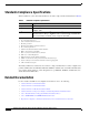
Specifications

14
Installation and Configuration Note for the Catalyst 4500 Series Supervisor Engine II-Plus TS
78-16551-01
Installing and Removing the Supervisor Engine
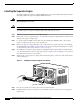
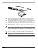
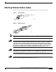
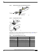
Figure 3 Captive Installation Screws and Ejector Levers
Step 3 Grasp the left and right ejector levers, and simultaneously pivot the levers outward to release the
supervisor engine from the backplane connector. Figure 3 shows a close-up of the right ejector lever.
Step 4 Grasp the front panel of the supervisor engine with one hand, and place your other hand under the carrier
to support and guide it out of the slot. Do not touch the printed circuit boards or connector pins.
Step 5 Carefully pull the supervisor engine straight out of the slot, keeping your other hand under the carrier to
guide it.
Step 6 Place the supervisor engine on an antistatic mat or antistatic foam, or immediately install it in another
slot 1 in another chassis.
Warning
Blank faceplates and cover panels serve three important functions: they prevent exposure to
hazardous voltages andcurrents insidethe chassis; they contain electromagnetic interference (EMI)
that might disrupt otherequipment; andthey directthe flow of cooling air through the chassis. Do not
operate the system unless all cards, faceplates, front covers, and rear covers are in place.
Statement 1029
Step 7 If the slot is to remain empty, install a switching-module filler plate (part number 800-00292-01).
Warning
Ultimate disposal of this product should be handled according to all national laws and regulations.
Statement 1040
113862
Captive
installation
screw
Ejector lever