
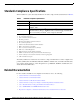
Specifications

13
Installation and Configuration Note for the Catalyst 4500 Series Supervisor Engine II-Plus TS
78-16551-01
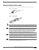
Installing and Removing the Supervisor Engine
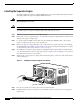
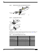
Step 9 Using the thumb and forefinger of each hand, simultaneously pivot in both ejector levers to fully seat the
supervisor engine in the backplane connector.
Caution Always use the ejector levers when installing or removing a supervisor engine. A supervisor engine that
is partially seated in the backplane will not function correctly.
Step 10 Use a screwdriver to tighten the captive installation screws on each end of the supervisor engine
faceplate.
To check the status of the module, perform these steps:
Step 1 Ensure that the LED labeled Status is green (module operational).
Step 2 When the switch is online, enter the show module command. Verify that the system acknowledges the
new module and that the module status is good.
Step 3 If the module is not operational, reseat it. If the module is still not operational, contact your customer
service representative.
Removing the Supervisor Engine
Warning
Invisible laser radiation may be emitted from disconnected fibers or connectors. Do not stare into
beams or view directly with optical instruments. Statement 1051
Warning
Hazardous voltage or energy is present on the backplane when the system is operating. Use caution
when servicing. Statement 1034
Caution To prevent ESD damage, handle supervisor engines by the carrier edges only.
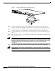
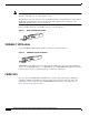
To remove a supervisor engine from a Catalyst 4500 series switch, perform these steps:
Step 1 Disconnect any network interface cables attached to the ports on the supervisor engine that you intend
to remove.
Step 2 Loosen the captive installation screws. (See Figure 3.)