
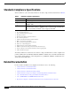
Specifications

12
Installation and Configuration Note for the Catalyst 4500 Series Supervisor Engine II-Plus TS
78-16551-01
Installing and Removing the Supervisor Engine
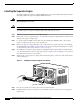
Installing the Supervisor Engine
The Catalyst 4500 series Supervisor Engine II-Plus TS is only used in Catalyst 4503 switches. Install
the Catalyst 4500 series Supervisor Engine II-Plus TS in slot 1.
Warning
Hazardous voltage or energy is present on the backplane when the system is operating. Use caution
when servicing. Statement 1034
Caution To prevent ESD damage, handle supervisor engines by the carrier edges only.
To install a supervisor engine in a Catalyst 4503 switch, follow this procedure:
Step 1 Take the necessary precautions to prevent ESD damage.
Step 2 Ensure that you have enough clearance to accommodate any interface equipment that you will connect
directly to the supervisor engine ports.
Step 3 Loosen the captive installation screws that secure the switching-module filler plate or the existing
supervisor engine (whichever is present), and remove it.
Step 4 Remove the supervisor engine filler plate or the existing supervisor engine from slot 1. If a switching
module filler plate was installed, save it for future use. If you are removing an existing supervisor engine,
see the “Removing the Supervisor Engine” section on page 13.
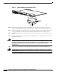
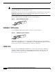
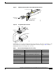
Step 5 To install the new supervisor engine, grasp the switching module front panel with one hand and place
your other hand under the carrier to support the supervisor engine, as shown in Figure 2. Do not touch
the printed circuit boards or connector pins.
Step 6 Align the edges of the supervisor engine carrier with the slot guides on the sides of the switch chassis,
as shown in Figure 2.
Figure 2 Installing the Supervisor Engine in the Chassis
Step 7 Pivot the two module ejector levers out and away from the faceplate.
Step 8 Carefully slide the supervisor engine into the slot until the notches on both ejector levers engage the
chassis sides.
1
13
1
13
1
13
1
13
113861
4506