
Specifications

11
Installation and Configuration Note for the Catalyst 4500 Series Supervisor Engine II-Plus TS
78-16551-01
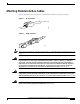
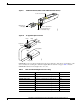
Installing and Removing the Supervisor Engine
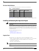
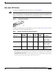
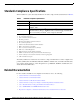
Maximum Cable Distances
Table 3 shows the maximum cable distances for transceiver speed and cable type.
Table 4 on page 17 provides cabling specifications for the SFPs that you install in the SFP port modules.
Installing and Removing the Supervisor Engine
Warning
Only trained and qualified personnel should be allowed to install, replace, orservice this equipment.
Statement 1030
All Catalyst 4500 series switches support hot swapping, which lets you install, remove, replace, and
rearrange supervisor engines and switching modules without powering off the system. When the system
detects that a switching module has been installed or removed, it runs diagnostic and discovery routines
automatically, acknowledges the presence or absence of the module, and resumes system operation with
no operator intervention.
This section contains the following subsections:
• Required Tools, page 11
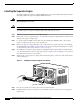
• Installing the Supervisor Engine, page 12
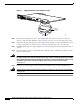
• Removing the Supervisor Engine, page 13
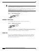
Required Tools
You will need these tools to install a supervisor engine in a Catalyst 4500 series switch:
• Number 1 and number 2 Phillips screwdrivers for the captive installation screws on most modules
• 3/16-inch flat-blade screwdriver for the captive installation screws on other modules
• Antistatic mat or antistatic foam
• Wrist strap or other grounding device
Note Whenever you handle supervisor engines, use a wrist strap or other grounding device to prevent ESD
damage.
Table 3 Maximum Cable Distances
Transceiver
Speed Cable Type Duplex Mode
Maximum Distance
Between Stations
10 Mbps Category 3 UTP Half or full 328 ft (100 m)
10 Mbps MMF Half or full 1.2 mi (2 km)
100 Mbps Category 5 UTP Half or full 328 ft (100 m)
100 Mbps MMF Half 1312 ft (400 m)
100 Mbps MMF Full 1.2 mi (2 km)