
Technical information


55
IPSec VPN Acceleration Services Module Installation and Configuration Note
78-14459-03 Rev C0
Configuring a VPN Using the VPN Module
Step 6 From interface configuration mode, create a Layer 3 inside interface VLAN and attach a crypto map as
follows:
a. Router# config t
Enter configuration commands, one per line. End with CNTL/Z.
b. Router(config)# interface vlan 513
c. Router(config-if)# description inside_interface_vlan_for_crypto_map
d. Router(config-if)# ip address 192.168.100.254 255.255.255.0
e. Router(config-if)# crypto map map101
f. Router(config-if)# no shutdown
Step 7 From interface configuration mode, add inside interface VLAN 513 as an allowed VLAN as follows:
a. Router(config-if)# interface gigabitethernet 5/1
b. Router(config-if)# description inside_vpn_module_trunk_port
c. Router(config-if)# switchport trunk allowed vlan add 513
Step 8 From interface configuration mode, connect the routed port to the inside interface VLAN as follows:
Router(config-if)# interface gigabitethernet 1/2
Router(config-if)# description outside_vlan_access_port
Router(config-if)# crypto connect vlan 513
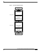
Configuring a VPN Trunk Port Connection
Caution When you configure an Ethernet port as a trunk port, all the VLANs are allowed on the trunk port by
default. This default configuration does not work well with the VPN module and causes network loops.
For detailed information on configuring trunks, see the “Trunks” section in the “Interaction with Other
Features” section on page 25.
This section describes how to configure the VPN module with a trunk port connection to the WAN router
(see Figure 12).
Note In the following example, the VPN module is installed in slot 5 (Gigabit Ethernet interfaces 5/1 and 5/2).