
Technical information


4
IPSec VPN Acceleration Services Module Installation and Configuration Note
78-14459-03 Rev C0
Understanding How the VPN Module Works
VPN Module Outside Port and Inside Port
The VPN module appears to the CLI as a module with two Gigabit Ethernet ports. The VPN module has
no external connectors; the Gigabit Ethernet ports connect the VPN module to the switch backplane and
Switch Fabric Module (if installed).
One Gigabit Ethernet port handles all the traffic going to and coming from the Catalyst switch outside
ports. This port is referred to as the VPN module outside port. The other Gigabit Ethernet port handles
all traffic going to and coming from the local LAN or inside ports. This port is referred to as the VPN
module inside port.
Note For detailed information on configuration guidelines and restrictions for the VPN module outside and
inside port, see the “VPN Module Configuration Guidelines” section on page 25.
Port VLAN and Interface VLAN
Your VPN configuration can have one or more Catalyst switch outside ports. To handle the packets from
multiple Catalyst switch outside ports, you need to direct the packets from multiple Catalyst switch
outside ports to the VPN module outside port by placing the Catalyst switch outside ports in a VLAN
with the outside port of the VPN module. This VLAN is referred to as the port VLAN. The port VLAN
is a Layer 2-only VLAN. You do not configure Layer 3 addresses or features on this VLAN; the packets
within the port VLAN are bridged by the PFC2.
Before the router can forward the packets using the correct routing table entries, the router needs to know
which interface that a packet was received on. For each port VLAN, you need to create another VLAN
so that the packets from every Catalyst switch outside port are presented to the router with the
corresponding VLAN ID. This VLAN contains only the VPN module inside port and is referred to as
the interface VLAN. The interface VLAN is a Layer 3-VLAN. You configure the Layer 3 address and
Layer 3 features, such as ACLs and the crypto map, to the interface VLAN.
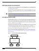
After you create and configure the port VLAN and the interface VLAN, you tie the VLANs together by
using a new CLI command (crypto connect vlan command). See the “Configuring a VPN Using the
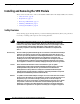
VPN Module” section on page 21 for detailed information. Figure 1 shows the port VLAN and interface
VLAN configurations.
Figure 1 Port VLAN and Interface VLAN Configuration Example
n
terface VLAN
(VLAN 1)
Interface VLAN
(VLAN 2)
Port VLAN
V
LAN 501)
Port VLAN
(VLAN 502)
W1
W2
Router
VPN module
79254