
Technical information

34
IPSec VPN Acceleration Services Module Installation and Configuration Note
78-14459-03 Rev C0
Configuring a VPN Using the VPN Module
• As with single VPN module deployments, you must properly configure each VPN module’s inside
and outside port. You can add an interface VLAN only to the inside port of one VPN module. Do
not add the same interface VLAN to the inside port of more than one VPN module.
Assigning interface VLANs to the inside ports of the VPN modules allow you to decide which VPN
module can be used to provide IPSec services for a particular interface VLAN.
Note There is no support for using more than one VPN module to do IPSec processing for a single
interface VLAN.
• SA-based load balancing is not supported.
• The crypto map local address command does not cause SA databases to be shared among multiple
VPN modules.
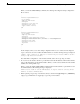
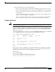
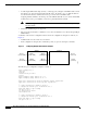
A summary of the switch 1 configuration that is used in the configuration example is as follows (see
Figure 9).
• A VPN module is in slot 2 and slot 3 of switch 1.
• In the configuration example, three exclamation points (!!!) precede descriptive comments.
Figure 9 Configuring Multiple VPN Modules Example
The following is a configuration example for switch 1:
crypto isakmp policy 1
encr 3des
hash md5
authentication pre-share
group 2
crypto isakmp key mykey address 10.8.1.1
crypto isakmp key mykey address 10.13.1.1
!
crypto ipsec transform-set xform1 ah-md5-hmac esp-des esp-sha-hmac
crypto ipsec transform-set xform2 esp-3des esp-sha-hmac
!
!!! crypto map applied to VLAN 12, which is
!!! assigned to "inside" port of VPN-SM in slot 3
crypto map cmap2 10 ipsec-isakmp
set peer 10.8.1.1
set transform-set xform1
match address 102
!
!!! crypto map applied to VLAN 20, which is
!!! assigned to "inside" port of VPN-SM in slot 2
crypto map cmap3 10 ipsec-isakmp
set peer 10.13.1.1
Switch 1
Host 1 FE 6/1
(10.9.1.3/24) (10.9.1.2/24)
GE 5/3
(switchport)
Host 3
(10.6.1.4)
Switch 2
GE 5/4
(switchport)
Host 2
(10.9.2.1/24)
Host 4
(10.6.2.1)
FE 6/2
(10.9.2.2/24)
94100