
Technical information

14
IPSec VPN Acceleration Services Module Installation and Configuration Note
78-14459-03 Rev C0
Installing and Removing the VPN Module
Warning
Before you install, operate, or service the system, read the
Regulatory Compliance and
Safety Information for the Catalyst 6500 Series Switches
publication or the
Regulatory
Compliance and Safety Information for the Cisco 7600 Series Internet Routers
publication. These publications contains important safety information you should know
before working with the system.
To install a VPN module in the chassis, perform these steps:
Step 1 Choose a slot for the VPN module.
Step 2 If possible, place VPN modules between empty slots that contain only module filler plates.
Step 3 Verify that the captive installation screws are tightened on all modules that are installed in the chassis.
This step assures that the EMI gaskets on all modules are fully compressed in order to maximize the
opening space for the new module or the replacement module.
Note If the captive installation screws are loose, the EMI gaskets on the installed
modules will push adjacent modules toward the open slot, reducing the opening
size and making it difficult to install the replacement module.
Step 4 Remove the module filler plate by removing the two Phillips pan-head screws from the filler plate. To
remove a module, see the “Removing a VPN Module” section on page 12.
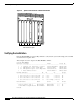
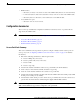
Step 5 Fully open both ejector levers on the new or replacement module. (See Figure 3.)
Step 6 Depending on the orientation of the slots in the chassis (horizontal or vertical), perform one of the two
following sets of substeps.
Horizontal slots
a. Position the VPN module in the slot. (See Figure 3.) Make sure that you align the sides of the
module carrier with the slot guides on each side of the slot.
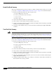
b. Carefully slide the VPN module into the slot until the EMI gasket along the top edge of the module
makes contact with the module in the slot above it and both ejector levers have closed to
approximately 45 degrees with respect to the module faceplate. (See Figure 4.)
c. Using the thumb and forefinger of each hand, grasp the two ejector levers and press down to create
a small (0.040 inch [1 mm]) gap between the module’s EMI gasket and the module above it. (See
Figure 4.)
Caution Do not exert too much pressure on the ejector levers because you will bend and damage
them.