IPSec VPN Acceleration Services Module Installation and Configuration Note Product Number: WS-SVC-IPSEC-1 This publication describes how to install and configure the IPSec Virtual Private Network (VPN) Acceleration Services Module in the Catalyst 6500 series switches and Cisco 7600 Series Internet Routers. Note Throughout this publication, the IPSec VPN Acceleration Services Module is referred to as the VPN module. Note Throughout this publication, the term crypto is used to refer to cryptographic.
Contents Contents This publication consists of these sections: • Understanding How the VPN Module Works, page 2 • Supported Features, page 5 • Hardware and Software Requirements, page 7 • Front Panel Description, page 9 • Installing and Removing the VPN Module, page 10 • Configuring a VPN Using the VPN Module, page 21 • Configuration Examples, page 58 • Regulatory Standards Compliance, page 98 • Obtaining Documentation, page 98 • Obtaining Technical Assistance, page 100 Understanding Ho
Understanding How the VPN Module Works When you configure a VPN on the Cisco routers, a packet is sent to a routed interface that is associated with an IP address. If the interface has an attached crypto map, the software checks that the packet is on an access control list (ACL) that is specified by the crypto map. If a match occurs, the packet is transformed (encrypted) before it is routed to the appropriate IPSec peer; otherwise, the packet is routed in the clear (unencrypted) state.
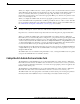
Understanding How the VPN Module Works VPN Module Outside Port and Inside Port The VPN module appears to the CLI as a module with two Gigabit Ethernet ports. The VPN module has no external connectors; the Gigabit Ethernet ports connect the VPN module to the switch backplane and Switch Fabric Module (if installed). One Gigabit Ethernet port handles all the traffic going to and coming from the Catalyst switch outside ports. This port is referred to as the VPN module outside port.
Supported Features Port VLAN 501 and port VLAN 502 are the port VLANs that are associated with the Catalyst switch outside ports W1 and W2. Interface VLAN 1 and interface VLAN 2 are the interface VLANs that correspond to port VLAN 501 and port VLAN 502. You configure the IP address, ACLs, and crypto map that apply to the Catalyst switch outside port W1 on interface VLAN 1. You configure the features that apply to the Catalyst switch outside port W2 on interface VLAN 2.
Supported Features • Capacity – 8000 tunnels (no IKE keepalive, no Dead-Peer-Detection [DPD]) – 5000 tunnels (no IKE keepalive, DPD okay) – 2000 tunnels (IKE keepalive) • Note DPD is supported in Cisco IOS Release 12.2(14)SY or later releases. Note Capacities are typically higher when IKE keepalive uses DPD.
Hardware and Software Requirements – PA-MC-2T1: 2-port multichannel T1 – PA-MC-8T1: 8-port multichannel T1 – PA-MC-T3: 1-port multichannel T3 – PA-MC-E3: 1-port multichannel E3 – PA-A3-T3: T3 ATM – PA-A3-OC3MM: OC3 ATM multimode – PA-A3-OC3SMI: OC3 ATM single-mode IR – PA-A3-OC3SML: OC3 ATM single-mode LR – PA-POS-OC3MM: OC3 POS multimode – PA-POS-OC3SMI: OC3 POS single-mode IR – PA-POS-OC3SML: OC3 POS single-mode LR – PA-H: 1-port HSSI – PA-2H: 2-port HSSI • You may have a VPN module in the same chassis
Hardware and Software Requirements Hardware Requirements This section lists the hardware requirements for the VPN module: • The following Catalyst 6500 series switches are supported: – Catalyst 6503 switch – Catalyst 6506 switch – Catalyst 6509 switch – Catalyst 6513 switch • Note With Cisco IOS Release 12.2(9)YO4, you can install only one VPN module per chassis. Note With Cisco IOS Release 12.2(14)SY or later releases, you can install up to 10 VPN modules per chassis.
Front Panel Description Note The FlexWAN module and the Optical Services Modules (OSMs) are not supported by Cisco IOS Release 12.2(9)YO4. Support for the FlexWAN module is added with Cisco IOS Release 12.2(14)SY (see the “Supported Features in Release 12.2(14)SY” section on page 6 for a complete list of supported port adapters). OSMs are not supported by Cisco IOS Release 12.2(14)SY. Front Panel Description The LED on the VPN module front panel (see Figure 2) indicates the status of the module.
Installing and Removing the VPN Module Installing and Removing the VPN Module These sections describe how to remove and install the VPN module in the Catalyst 6500 series switches: • Safety Overview, page 10 • Required Tools, page 12 • Removing a VPN Module, page 12 • Installing a VPN Module, page 13 • Verifying the Installation, page 20 Safety Overview Safety warnings appear throughout these procedures indicating tasks that may harm you if performed incorrectly.
Installing and Removing the VPN Module Warnung Avvertenza Dieses Warnsymbol bedeutet Gefahr. Sie befinden sich in einer Situation, die zu einer Körperverletzung führen könnte. Bevor Sie mit der Arbeit an irgendeinem Gerät beginnen, seien Sie sich der mit elektrischen Stromkreisen verbundenen Gefahren und der Standardpraktiken zur Vermeidung von Unfällen bewußt.
Installing and Removing the VPN Module Caution Warning During this procedure, wear grounding wrist straps to avoid ESD damage to the card. Do not directly touch the backplane with your hand or any metal tool, or you could shock yourself.
Installing and Removing the VPN Module Step 2 Loosen the two captive installation screws on the VPN module. Step 3 Depending on the orientation of the slots in the chassis (horizontal or vertical), perform one of the following two sets of steps. Horizontal slots a. Place your thumbs on the left and right ejector levers, and simultaneously rotate the levers outward to unseat the module from the backplane connector. b.
Installing and Removing the VPN Module Warning Before you install, operate, or service the system, read the Regulatory Compliance and Safety Information for the Catalyst 6500 Series Switches publication or the Regulatory Compliance and Safety Information for the Cisco 7600 Series Internet Routers publication. These publications contains important safety information you should know before working with the system.
Installing and Removing the VPN Module Vertical slots Caution a. Position the VPN module in the slot. (See Figure 6.) Make sure that you align the sides of the switching-module carrier with the slot guides on the top and bottom of the slot. b. Carefully slide the VPN module into the slot until the EMI gasket along the right edge of the module makes contact with the module in the slot adjacent to it and both ejector levers have closed to approximately 45 degrees with respect to the module faceplate.
Installing and Removing the VPN Module Figure 8 Ejector Lever Closure in a Vertical Slot Chassis FAN STATUS T M LE G O T M EM US R NS SE ST AT RE PW SY CO ST CO EM ST SY O NS PW LE STA R T CONSOLE CONSOLE VE TI AC SE T M RE G S M TU CONSOLE PORT MODE CONSOLE PORT MODE PCMCIA PCMCIA EJECT EJECT 100% Switch Switch 1% 1% 100% Load Load PORT 1 PORT 1 XT WS-X6K-SUP2-2GE SUPERVISOR2 US AT ST WS-X6K-SUP2-2GE SUPERVISOR2 WS-X6224 24 PORT 100FX NE SE LE CT 63587 P
Configuring a VPN Using the VPN Module Configuring a VPN Using the VPN Module These sections describe how to configure a VPN using the VPN module: • Hardware- and Software-Based Cryptographic Modes, page 21 • Configuration Summaries, page 23 • VPN Module Configuration Guidelines, page 25 • Port Configuration Procedures, page 51 – Configuring a VPN Access Port Connection, page 52 – Configuring a VPN Routed Port Connection, page 54 – Configuring a VPN Trunk Port Connection, page 55 – Displaying the VP
Configuring a VPN Using the VPN Module Note Switching to the software-based cryptographic mode (by entering the no crypto connect vlan command) does not automatically change the configuration and enable software-based cryptographic operation. To enable software-based cryptographic mode and have it function correctly, you have to remove the VPN module configuration and reconfigure the switch for software-based cryptographic operation.
Configuring a VPN Using the VPN Module • WAN interface: – shut down (on reload)—No SAs are created on the VPN module (must do a no shut down first). – no shut down (first no shut down issued after a reload)—SAs are created on the VPN module. – shut down (after a no shut down)—SAs remain active on the VPN module. • Access/trunk mode ports: – shut down—SAs are never removed.
Configuring a VPN Using the VPN Module Routed Port Mode Summary This section summarizes the steps that are required to configure a Catalyst switch outside port as a routed port (see the “Configuring a VPN Routed Port Connection” section on page 54 for detailed information): 1. Perform the following standard Cisco IOS encryption tasks: a. Create an IKE policy, if necessary. b. Create a preshared key entry, if necessary. c. Create an ACL. d. Create a crypto map. 2.
Configuring a VPN Using the VPN Module VPN Module Configuration Guidelines Use the guidelines in the following sections when configuring a VPN using the VPN module: • Interaction with Other Features, page 25 • Preventing VPN Module Misconfigurations, page 26 • Miscellaneous Guidelines, page 28 • Handling Multicast Traffic, page 29 • Configuring MTU Settings, page 30 • Configuring Trunk Ports, page 31 • Configuring the VPN Module Inside Port and Outside Port, page 33 • Using Multiple VPN Modu
Configuring a VPN Using the VPN Module • Switched Port Analyzer (SPAN) Interaction with the SPAN feature is as follows: – If the SPAN session is set up to copy all the traffic from the VPN module inside port, then all the traffic before encryption and after decryption is sent to the SPAN port. – If the SPAN session is set up to copy all the traffic from the VPN module outside port, then all the traffic before decryption and after encryption is sent to the SPAN port.
Configuring a VPN Using the VPN Module When you enter the write memory command, the following misconfigured startup-configuration file is created: . . . interface GigabitEthernet1/1 no ip address snmp trap link-status switchport switchport access vlan 200 switchport mode access crypto connect vlan 100 end . . .
Configuring a VPN Using the VPN Module Miscellaneous Guidelines Follow these configuration guidelines for configuring a VPN using the VPN module: • Loopback interfaces Attaching a crypto map set to a loopback interface is not supported. However, you can maintain an IPSec security association database independent of physical ingress/egress interfaces with the VPN module by entering the crypto map map-name local-address interface command.
Configuring a VPN Using the VPN Module Handling Multicast Traffic In Cisco IOS Release 12.2(9)YO and later releases, when a chassis contains a Switch Fabric Module the VPN module drops all multicast traffic. This action does not occur if there is no Switch Fabric Module installed. To handle this multicast traffic issue, in Cisco IOS Release 12.
Configuring a VPN Using the VPN Module • If you insert a VPN module in a chassis that is in compact mode and the VPN module uses one of the automatically configured SPAN sessions without any problems, the system allows you to remove the VPN module and then manually configure both SPAN sessions. However, if you reinsert the VPN module, it is put in compact mode. In this situation, all multicast traffic that is sourced from the VPN module is dropped.
Configuring a VPN Using the VPN Module • The interface MTU setting is greater than 1500 bytes: – If the received packet length is greater than the global MTU value, the packets are dropped. – If the received packet length is less than or equal to the global MTU value, routing is performed and the outgoing interface is determined as the result of routing.
Configuring a VPN Using the VPN Module To remove the interface VLAN from the VLAN list, enter the following commands: Router# conf t Router(config)# int g1/1 Router(config-if)# no switchport mode trunk Router(config-if)# switchport trunk allowed vlan 1 Router(config-if)# switchport mode trunk Router(config-if)# switchport trunk allowed vlan add vlan-list Note VLANs in the vlan-list must not include any interface VLANs.
Configuring a VPN Using the VPN Module Configuring the VPN Module Inside Port and Outside Port Follow these guidelines for configuring the VPN module inside port and outside port: • Do not configure the VPN module outside port. Cisco IOS software configures the port automatically. • Do not change the port characteristics of the VPN module inside port.
Configuring a VPN Using the VPN Module • As with single VPN module deployments, you must properly configure each VPN module’s inside and outside port. You can add an interface VLAN only to the inside port of one VPN module. Do not add the same interface VLAN to the inside port of more than one VPN module. Assigning interface VLANs to the inside ports of the VPN modules allow you to decide which VPN module can be used to provide IPSec services for a particular interface VLAN.
Configuring a VPN Using the VPN Module set transform-set xform2 match address 103 ! !!! "inside" port of VPN-SM in slot 2: !!! encrypts traffic from VLAN 20, sending encrypted !!! packets to VLAN 19 via "outside" port Gig2/2 interface GigabitEthernet2/1 no ip address flowcontrol receive on switchport switchport trunk encapsulation dot1q switchport trunk allowed vlan 1,20,1002-1005 switchport mode trunk cdp enable ! !!! "outside" port of VPN-SM in slot 2: !!! decrypts traffic from VLAN 19, sending decrypted
Configuring a VPN Using the VPN Module crypto connect vlan 20 ! !!! "interface" VLAN, assigned to VPN-SM on slot 2 interface Vlan20 ip address 10.13.1.2 255.255.0.0 crypto map cmap3 ! !!! connected to Host 1 interface FastEthernet6/1 ip address 10.9.1.2 255.255.255.0 ! !!! connected to Host 2 interface FastEthernet6/2 ip address 10.9.2.2 255.255.255.
Configuring a VPN Using the VPN Module For complete configuration information for Cisco IOS IPSec stateful failover support, refer to this URL: http://www.cisco.com/en/US/products/sw/iosswrel/ps5012/products_feature_guide09186a0080116d4c.html Follow these guidelines when configuring IPSec stateful failover: • When configuring an IPSec stateful failover with the VPN module, note that all VPN module configuration rules apply.
Configuring a VPN Using the VPN Module Active# show run Building configuration... Current configuration : 2235 bytes ! version 12.2 service timestamps debug uptime service timestamps log uptime no service password-encryption ! hostname Active ! boot system flash sup-bootflash: ! redundancy main-cpu auto-sync standard ip subnet-zero ! ! no ip domain-lookup ! ! ssp group 100 remote 40.0.0.
Configuring a VPN Using the VPN Module standby track GigabitEthernet1/1 ! interface GigabitEthernet3/1 mtu 4500 no ip address snmp trap link-status switchport switchport trunk encapsulation dot1q switchport trunk allowed vlan 1,4,1002-1005 switchport mode trunk flowcontrol receive on cdp enable ! interface GigabitEthernet3/2 mtu 4500 no ip address snmp trap link-status switchport switchport trunk encapsulation dot1q switchport trunk allowed vlan 1,1002-1005 switchport mode trunk flowcontrol receive on cdp
Configuring a VPN Using the VPN Module The following is a configuration example for the standby chassis that is configured for IPSec stateful failover: StandBy# show run Building configuration... Current configuration : 2236 bytes ! version 12.2 service timestamps debug uptime service timestamps log uptime no service password-encryption ! hostname StandBy ! boot system flash sup-bootflash: ! redundancy main-cpu auto-sync standard ip subnet-zero ! ! no ip domain-lookup ! ! ssp group 100 remote 40.0.0.
Configuring a VPN Using the VPN Module standby standby standby standby standby delay minimum 35 reload 60 ip 40.0.0.
Configuring a VPN Using the VPN Module Using IPSec NAT Transparency Note This section applies to VPN modules running Cisco IOS Release 12.2(14)SY or later releases. For complete configuration information for Cisco IOS IPSec NAT transparency support, refer to this URL: http://www.cisco.com/en/US/products/sw/iosswrel/ps1839/products_feature_guide09186a0080110bca.html There is no VPN module-specific configuration requirements or restrictions for IPSec NAT transparency.
Configuring a VPN Using the VPN Module The following is a configuration example of the router-side configuration: ! version 12.
Configuring a VPN Using the VPN Module redundancy main-cpu auto-sync running-config auto-sync standard ! interface GigabitEthernet2/1 no ip address switchport switchport trunk encapsulation dot1q switchport trunk allowed vlan 1,513,1002-1005 switchport mode trunk ! interface GigabitEthernet2/2 no ip address shutdown ! interface GigabitEthernet6/1 no ip address flowcontrol receive on flowcontrol send off switchport switchport trunk encapsulation dot1q switchport trunk allowed vlan 1,513,1002-1005 switchport
Configuring a VPN Using the VPN Module Using Dead-Peer-Detection Note This section applies to VPN modules running Cisco IOS Release 12.2(14)SY or later releases. For complete configuration information for Cisco IOS Dead-Peer-Detection (DPD) support, refer to this URL: http://www.cisco.com/en/US/products/sw/secursw/ps2308/products_user_guide_chapter09186a00800ecb3d.html Using WAN Interfaces Note This section applies to VPN modules running Cisco IOS Release 12.2(14)SY or later releases.
Configuring a VPN Using the VPN Module Crypto Connection for a Channelized T3 Port Adapter in the FlexWAN Module The configuration for this example is as follows: • The FlexWAN module is in slot 2. • The channelized T3 port adapter is in bay 0. • The VPN module is in slot 5.
Configuring a VPN Using the VPN Module crypto connect vlan 206 ! interface Serial2/0/0/11:0 no ip address encapsulation ppp no cdp enable ppp chap hostname m1 ppp multilink multilink-group 1 ! interface Serial2/0/0/12:0 no ip address encapsulation ppp no cdp enable ppp chap hostname m1 ppp multilink multilink-group 1 ! interface Serial2/0/0/13:0 no ip address encapsulation ppp no cdp enable ppp chap hostname m1 ppp multilink multilink-group 1 ! interface GigabitEthernet5/1 no ip address flowcontrol receive
Configuring a VPN Using the VPN Module ! interface GigabitEthernet5/1 no ip address flowcontrol receive on flowcontrol send off switchport switchport trunk encapsulation dot1q switchport trunk allowed vlan 1,101,1002-1005 switchport mode trunk cdp enable ! interface ATM6/0/0 no ip address atm clock INTERNAL ! interface ATM6/0/0.101 point-to-point pvc 1/101 ! crypto connect vlan 101 ! interface Vlan101 ip address 192.168.101.1 255.255.255.
Configuring a VPN Using the VPN Module crypto connect vlan 16 ! interface Vlan16 ip address 192.168.16.1 255.255.255.0 no mop enabled Using Look-Ahead Fragmentation Note This section applies to VPN modules running Cisco IOS Release 12.2(14)SY or later releases. Follow these guidelines for using Look-Ahead Fragmentation (LAF): • Large packets can increase the IPSec packet size beyond the MTU causing the IPSec packets to be fragmented.
Configuring a VPN Using the VPN Module Follow these guidelines for configuring GRE tunneling: • Caution If routing information changes and the GRE-encapsulated packets no longer egress through an interface VLAN, the VPN module yields the GRE tunnel. After the VPN module yields the tunnel, the route processor resumes encapsulation and decapsulation which increases CPU utilization on the route processor. Ensure that your GRE tunnel configuration does not overload the route processor.
Configuring a VPN Using the VPN Module Using QoS Note This section applies to VPN modules running Cisco IOS Release 12.2(14)SY or later releases. The VPN module uses the QoS capabilities of the Catalyst 6500 series switches and Cisco 7600 Series Internet Router software. Before configuring QoS for the VPN module, refer to this URL: http://www.cisco.com/en/US/products/hw/switches/ps700/products_tech_note09186a008014a29f.
Configuring a VPN Using the VPN Module Configuring a VPN Access Port Connection This section describes how to configure the VPN module with an access port connection to the WAN router (see Figure 10). Note In the following example, the VPN module is installed in slot 5 (Gigabit Ethernet interfaces 5/1 and 5/2). To configure an access port connection to the WAN router, follow these steps: Step 1 Create an IKE policy, if necessary. Step 2 Create a preshared key entry, if necessary.
Configuring a VPN Using the VPN Module Step 5 From privileged EXEC mode, add an inside interface VLAN (VLAN 53) and an outside access port VLAN (VLAN 54) to the VLAN database as follows: a. Router# config t Enter configuration commands, one per line. b. End with CNTL/Z. Router(config)# vlan 53 Router(config-vlan)# name inside_interface_vlan Router(config-vlan)# exit Router(config)# c.
Configuring a VPN Using the VPN Module Configuring a VPN Routed Port Connection This section describes how to configure the VPN module with a routed port connection to the WAN router (see Figure 11). Note A routed port uses a hidden VLAN. Note In the following example, the VPN module is installed in slot 5 (Gigabit Ethernet interfaces 5/1 and 5/2). To configure a routed port connection to the WAN router, follow these steps: Step 1 Create an IKE policy, if necessary.
Configuring a VPN Using the VPN Module Step 6 From interface configuration mode, create a Layer 3 inside interface VLAN and attach a crypto map as follows: a. Router# config t Enter configuration commands, one per line. Step 7 Step 8 End with CNTL/Z. b. Router(config)# interface vlan 513 c. Router(config-if)# description inside_interface_vlan_for_crypto_map d. Router(config-if)# ip address 192.168.100.254 255.255.255.0 e. Router(config-if)# crypto map map101 f.
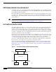
Configuring a VPN Using the VPN Module Figure 12 Trunk Port Configuration Example LAN interface Gigabit Ethernet 1/1 Interface VLAN 171 (192.168.100.254) WAN router 79257 Port VLAN 271 Gigabit Ethernet 1/2 WAN interface trunk port To configure a trunk port connection to the WAN router, follow these steps: Step 1 Create an IKE policy, if necessary. Step 2 Create a preshared key entry, if necessary. Step 3 Create an ACL. Step 4 Create a crypto map.
Configuring a VPN Using the VPN Module Step 6 From interface configuration mode, create a Layer 3 inside interface VLAN and attach a crypto map as follows: a. Router# config t Enter configuration commands, one per line. Step 7 End with CNTL/Z. b. Router(config)# interface vlan 171 c. Router(config-if)# description inside_interface_vlan_for_crypto_map d. Router(config-if)# ip address 192.168.100.254 255.255.255.0 e. Router(config-if)# crypto map map101 f.
Configuration Examples Displaying the VPN Running State Use the show crypto vlan command to display the VPN running state.
Configuration Examples Catalyst Switch 1 (Access Port) The Catalyst switch 1 configuration is as follows (see Figure 13): ! version 12.
Configuration Examples no ip address flowcontrol receive on ! interface GigabitEthernet5/2 switchport switchport trunk encapsulation dot1q switchport trunk allowed vlan 1,54,1002-1005 switchport mode trunk no ip address flowcontrol receive on ! interface Vlan1 no ip address shutdown ! interface Vlan53 ip address 192.168.100.253 255.255.255.0 crypto map MAP-101 ! interface Vlan54 no ip address crypto connect vlan 53 ! ip classless ip route 10.83.3.0 255.255.255.0 192.168.100.
Configuration Examples Figure 13 Access Port Configuration Example Router (10.83.3.1) LAN interface Gigabit Ethernet 1/1 (10.83.3.254) Catalyst switch 2 Interface VLAN 53 (192.168.100.254) Port VLAN 54 Gigabit Ethernet 1/2 WAN interface access port WAN interface access port Gigabit Ethernet 1/2 Catalyst switch 1 Interface VLAN 53 (192.168.100.253) Port VLAN 54 Router (10.80.1.1) 79258 Gigabit Ethernet 1/1 (10.80.1.
Configuration Examples Catalyst Switch 2 (Access Port) The Catalyst switch 2 configuration is as follows (see Figure 13): ! version 12.
Configuration Examples interface GigabitEthernet5/1 switchport switchport trunk encapsulation dot1q switchport trunk allowed vlan 1,53,1002-1005 switchport mode trunk no ip address flowcontrol receive on ! interface GigabitEthernet5/2 switchport switchport trunk encapsulation dot1q switchport trunk allowed vlan 1,54,1002-1005 switchport mode trunk no ip address flowcontrol receive on ! interface Vlan1 no ip address shutdown ! interface Vlan53 ip address 192.168.100.254 255.255.255.
Configuration Examples Catalyst Switch 1 (Routed Port) The Catalyst switch 1 configuration is as follows (see Figure 14): ! version 12.
Configuration Examples interface GigabitEthernet5/2 switchport switchport trunk encapsulation dot1q switchport trunk allowed vlan 1,1002-1005 switchport mode trunk no ip address flowcontrol receive on ! interface Vlan1 no ip address shutdown ! interface Vlan513 ip address 192.168.100.253 255.255.255.0 crypto map MAP-101 ! ip classless ip route 10.83.3.0 255.255.255.0 192.168.100.254 no ip http server ! ! ip access-list extended AEO-101 permit ip 10.80.0.0 0.0.255.255 10.83.0.0 0.0.255.
Configuration Examples Figure 14 Routed Port Configuration Example Router (10.83.3.1) LAN interface Gigabit Ethernet 1/1 (10.83.3.254) Catalyst switch 2 Interface VLAN 513 (192.168.100.254) Gigabit Ethernet 1/2 WAN interface routed port WAN interface routed port Gigabit Ethernet 1/2 Catalyst switch 1 Interface VLAN 513 (192.168.100.253) Router (10.80.1.1) 79259 Gigabit Ethernet 1/1 (10.80.1.
Configuration Examples redundancy main-cpu auto-sync standard diagnostic level complete ip subnet-zero ! ! no ip domain-lookup ! ip ssh time-out 120 ip ssh authentication-retries 3 ! ! crypto isakmp policy 1 encr 3des hash md5 authentication pre-share group 2 crypto isakmp key Jolly-Good-Fellow address 192.168.100.253 ! ! crypto ipsec transform-set TS-101 esp-3des esp-sha-hmac ! crypto map MAP-101 10 ipsec-isakmp set peer 192.168.100.
Configuration Examples interface Vlan1 no ip address shutdown ! interface Vlan513 ip address 192.168.100.254 255.255.255.0 crypto map MAP-101 ! ip classless ip route 10.80.1.0 255.255.255.0 192.168.100.253 no ip http server ! ! ip access-list extended AEO-101 permit ip 10.83.0.0 0.0.255.255 10.80.0.0 0.0.255.
Configuration Examples ! crypto isakmp policy 1 encr 3des hash md5 authentication pre-share group 2 crypto isakmp key Jolly-Good-Fellow address 192.168.100.254 ! ! crypto ipsec transform-set TS-101 esp-3des esp-sha-hmac ! crypto map MAP-101 10 ipsec-isakmp set peer 192.168.100.254 set security-association lifetime kilobytes 10000 set security-association lifetime seconds 86000 set transform-set TS-101 match address AEO-101 ! ! no spanning-tree vlan 171 ! ! ! interface GigabitEthernet1/1 ip address 10.80.1.
Configuration Examples ! ! ip access-list extended AEO-101 permit ip 10.80.0.0 0.0.255.255 10.83.0.0 0.0.255.255 ! ! line con 0 line vty 0 4 login ! end Figure 15 Trunk Port Configuration Example Router (10.83.3.1) LAN interface Gigabit Ethernet 1/1 (10.83.3.254) Catalyst switch 2 Port VLAN 271 Interface VLAN 171 (192.168.100.254) Gigabit Ethernet 1/2 WAN interface trunk port WAN interface trunk port Gigabit Ethernet 1/2 Catalyst switch 1 Interface VLAN 171 (192.168.100.
Configuration Examples Catalyst Switch 2 (Trunk Port) The Catalyst switch 2 configuration is as follows (see Figure 15): ! version 12.
Configuration Examples interface GigabitEthernet5/1 switchport switchport trunk encapsulation dot1q switchport trunk allowed vlan 1,171,1002-1005 switchport mode trunk no ip address flowcontrol receive on ! interface GigabitEthernet5/2 switchport switchport trunk encapsulation dot1q switchport trunk allowed vlan 1,271,1002-1005 switchport mode trunk no ip address flowcontrol receive on ! interface Vlan1 no ip address shutdown ! interface Vlan171 ip address 192.168.100.254 255.255.255.
Configuration Examples ATM Ports Note This section applies to VPN modules running Cisco IOS Release 12.2(14)SY or later releases. These sections describe ATM port configuration: • Catalyst Switch 1 (ATM Port), page 73 • Catalyst Switch 2 (ATM Port), page 77 Catalyst Switch 1 (ATM Port) The Catalyst switch 1 configuration is as follows: version 12.
Configuration Examples auto-sync standard ! controller T3 2/0/0 t1 1 channel-group 0 timeslots 1-24 t1 2 channel-group 0 timeslots 1-24 . . . t1 27 channel-group 0 timeslots 1-24 t1 28 channel-group 0 timeslots 1-24 ! ! vlan 1 tb-vlan1 1002 tb-vlan2 1003 ! vlan 2-1001 ! vlan 1002 tb-vlan1 1 tb-vlan2 1003 ! vlan 1003 tb-vlan1 1 tb-vlan2 1002 backupcrf enable ! vlan 1004 bridge 1 stp type ibm ! ! interface Loopback7 ip address 7.7.7.7 255.255.255.
Configuration Examples crypto connect vlan 6 ! interface Serial2/0/0/2:0 no ip address no fair-queue no cdp enable . . . interface Serial2/0/0/27:0 no ip address no fair-queue no cdp enable ! interface Serial2/0/0/28:0 no ip address no fair-queue no cdp enable ! interface FastEthernet3/1 ip address 10.80.1.254 255.255.255.0 no cdp enable ! interface FastEthernet3/2 no ip address shutdown . . . ! interface FastEthernet3/38 no ip address shutdown ! interface FastEthernet3/39 ip address 3.5.39.7 255.255.255.
Configuration Examples cdp enable ! interface GigabitEthernet5/2 no ip address flowcontrol receive on switchport switchport trunk encapsulation dot1q switchport trunk allowed vlan 1,1002-1005 switchport mode trunk cdp enable ! interface ATM6/0/0 no ip address atm clock INTERNAL ! interface ATM6/0/0.101 point-to-point pvc 0/101 crypto connect vlan 101 ! interface POS6/1/0 no ip address shutdown ! interface Vlan1 no ip address shutdown ! interface Vlan6 ip address 192.168.6.1 255.255.255.
Configuration Examples Catalyst Switch 2 (ATM Port) The Catalyst switch 2 configuration is as follows: version 12.2 service timestamps debug uptime service timestamps log uptime no service password-encryption ! hostname Router-2 ! boot system flash bootflash:c6k logging snmp-authfail enable password lab ! ip subnet-zero ! ! no ip domain-lookup ip host charles 10.10.20.1 ip host tftp 223.255.254.
Configuration Examples multilink-group 1 . . . ! interface Multilink6 no ip address ppp multilink multilink-group 6 ! interface GigabitEthernet1/1 no ip address shutdown ! interface GigabitEthernet1/2 no ip address shutdown ! interface Serial3/0/0/1:0 no ip address no fair-queue . . . ! interface Serial3/0/0/28:0 no ip address no fair-queue ! interface ATM4/0/0 no ip address atm clock INTERNAL ! interface ATM4/0/0.
Configuration Examples ip address 10.10.20.254 255.255.255.0 ! interface FastEthernet8/3 no ip address shutdown . . . ! interface FastEthernet8/47 no ip address shutdown ! interface FastEthernet8/48 no ip address shutdown ! interface Vlan1 no ip address shutdown ! interface Vlan101 ip address 192.168.101.2 255.255.255.0 no mop enabled crypto map cwan-101 ! ip classless ip route 172.16.1.101 255.255.255.255 192.168.101.
Configuration Examples Catalyst Switch 1 (Frame Relay Port) The Catalyst switch 1 configuration is as follows: version 12.2 service timestamps debug uptime service timestamps log uptime no service password-encryption service internal ! hostname Router-1 ! boot system flash bootflash:c6k logging snmp-authfail enable password lab ! vtp mode transparent ip subnet-zero ! ! no ip domain-lookup ip host ockham 172.16.1.1 ip host tftp 10.80.1.1 ip host tftp-serv 10.80.1.
Configuration Examples vlan 1 tb-vlan1 1002 tb-vlan2 1003 ! vlan 2-1001 ! vlan 1002 tb-vlan1 1 tb-vlan2 1003 ! vlan 1003 tb-vlan1 1 tb-vlan2 1002 backupcrf enable ! vlan 1004 bridge 1 stp type ibm ! ! interface Multilink1 no ip address no cdp enable ppp multilink multilink-group 1 . . . ! interface Multilink6 no ip address no cdp enable ppp multilink multilink-group 6 ! interface GigabitEthernet1/1 no ip address shutdown ! interface GigabitEthernet1/2 mtu 4500 ip address 11.22.1.1 255.255.255.
Configuration Examples interface FastEthernet3/2 no ip address shutdown . . . ! interface FastEthernet3/38 no ip address shutdown ! interface FastEthernet3/39 ip address 3.5.39.7 255.255.255.0 no cdp enable ! interface FastEthernet3/40 ip address 3.5.40.7 255.255.255.0 no cdp enable ! interface FastEthernet3/41 no ip address shutdown . . . ! interface FastEthernet3/46 no ip address shutdown ! interface FastEthernet3/47 ip address 172.16.1.254 255.255.255.
Configuration Examples clock source internal frame-relay intf-type dce ! interface POS6/1/0.16 point-to-point no cdp enable frame-relay interface-dlci 16 crypto connect vlan 16 ! interface Vlan1 no ip address shutdown ! interface Vlan16 ip address 192.168.16.1 255.255.255.0 no mop enabled crypto map cwan-16 ! ip classless ip route 10.10.20.16 255.255.255.255 192.168.16.2 no ip http server no ip http secure-server ! ! ip access-list extended acl-16 permit ip host 172.16.1.16 host 10.10.20.
Configuration Examples ! crypto isakmp policy 1 encr 3des hash md5 authentication pre-share group 2 crypto isakmp key foobar address 192.168.0.0 255.255.0.0 ! ! crypto ipsec transform-set ts-cwan esp-3des esp-sha-hmac ! crypto map cwan-16 10 ipsec-isakmp set peer 192.168.16.
Configuration Examples no ip address no fair-queue ! interface ATM4/0/0 no ip address shutdown ! interface POS4/1/0 no ip address encapsulation frame-relay no keepalive clock source internal ! interface POS4/1/0.
Configuration Examples no ip http server no ip http secure-server ! ! ip access-list extended acl-16 permit ip host 10.10.20.16 host 172.16.1.
Configuration Examples flowcontrol send off switchport switchport trunk encapsulation dot1q switchport trunk allowed vlan 1,2,1002-1005 switchport mode trunk cdp enable ! interface Vlan2 ip address 192.168.1.254 255.255.255.0 no mop enabled crypto map cm1 ! interface Vlan502 no ip address crypto connect vlan 2 ! interface Tunnel1 ip address 10.1.1.254 255.255.255.0 tunnel source vlan1 tunnel destination 192.168.1.1 ! ip route 6.0.0.0 255.255.255.0 Tunnel1 ! ip access-list extended acl1 permit gre host 192.
Configuration Examples switchport mode trunk cdp enable ! interface Vlan2 ip address 192.168.1.1 255.255.255.0 no mop enabled crypto map cm1 ! interface Vlan502 no ip address crypto connect vlan 2 ! interface Tunnel1 ip address 10.1.1.1 255.255.255.0 tunnel source vlan2 tunnel destination 192.168.1.254 ! ip route 5.0.0.0 255.255.255.0 Tunnel1 ! ip access-list extended acl1 permit gre host 192.168.1.1 host 192.168.1.254 ! HSRP For complete configuration information for HSRP, refer to this URL: http://www.
Configuration Examples ! boot system flash sup-bootflash: ! redundancy main-cpu auto-sync standard ip subnet-zero ! ! no ip domain-lookup ! ! no mls ip multicast aggregate no mls ip multicast non-rpf cef ! crypto isakmp policy 1 encr 3des authentication pre-share crypto isakmp key NEEWOMM address 0.0.0.0 0.0.0.
Configuration Examples no ip address snmp trap link-status switchport switchport trunk encapsulation dot1q switchport trunk allowed vlan 1,1002-1005 switchport mode trunk flowcontrol receive on cdp enable ! interface Vlan1 no ip address shutdown ! interface Vlan4 ip address 172.16.31.1 255.255.255.0 standby delay minimum 35 reload 60 standby ip 172.16.31.
Configuration Examples ! ! no ip domain-lookup ! ! no mls ip multicast aggregate no mls ip multicast non-rpf cef ! crypto isakmp policy 1 encr 3des authentication pre-share crypto isakmp key NEEWOMM address 0.0.0.0 0.0.0.0 ! ! crypto ipsec security-association lifetime seconds 86400 ! crypto ipsec transform-set TS1 esp-3des esp-sha-hmac ! crypto map ha ha replay-interval inbound 10 outbound 1000 crypto map ha 10 ipsec-isakmp set peer 172.16.31.
Configuration Examples cdp enable ! interface Vlan1 no ip address shutdown ! interface Vlan4 ip address 172.16.31.2 255.255.255.0 standby delay minimum 35 reload 60 standby ip 172.16.31.100 standby timers 1 3 standby preempt standby name KNIGHTSOFNI standby track GigabitEthernet1/1 standby track GigabitEthernet1/2 crypto map ha redundancy KNIGHTSOFNI ! ip classless ip route 10.11.1.1 255.255.255.255 172.16.31.3 no ip http server ip pim bidir-enable ! access-list 101 permit ip host 40.0.0.3 host 10.11.1.
Configuration Examples crypto isakmp policy 1 encr 3des authentication pre-share crypto isakmp key NEEWOMM address 0.0.0.0 0.0.0.0 ! crypto ipsec security-association lifetime seconds 86400 ! crypto ipsec transform-set TS1 esp-3des esp-sha-hmac ! crypto map ha 10 ipsec-isakmp set peer 172.16.31.100 set transform-set TS1 match address 101 ! spanning-tree extend system-id ! ! ! interface Loopback1 ip address 10.11.1.1 255.255.255.
Configuration Examples ! line con 0 line vty 0 4 login transport input lat pad mop telnet rlogin udptn nasi ssh ! end QoS These sections provide configuration examples for QoS: • Switch 1 Configuration, page 94 • Switch 2 Configuration, page 96 A summary of the switch configuration that is used in the examples is as follows (see Figure 16): • The VPN module is in slot 3 on both switches. • An IPSec tunnel that is between switch 1 and switch 2 encrypts all traffic.
Configuration Examples !!! Enables qos globally mls qos ! crypto isakmp policy 10 authentication pre-share crypto isakmp key 12345 address 192.0.0.2 ! ! crypto ipsec transform-set 3des_sha1_ts esp-3des esp-sha-hmac ! crypto map cmap2 100 ipsec-isakmp set peer 192.0.0.2 set transform-set 3des_sha1_ts match address acl0 ! ! spanning-tree extend system-id no spanning-tree vlan 2 ! redundancy mode rpr-plus main-cpu auto-sync running-config auto-sync standard ! ! ! interface GigabitEthernet1/1 ip address 12.0.
Configuration Examples switchport trunk allowed vlan 1,1002-1005 switchport mode trunk cdp enable spanning-tree portfast trunk ! interface Vlan2 ip address 192.0.0.1 255.255.255.0 no mop enabled crypto map cmap2 ! ip classless ip route 13.0.0.0 255.0.0.0 192.0.0.
Configuration Examples crypto ipsec transform-set 3des_sha1_ts esp-3des esp-sha-hmac ! crypto map cmap2 100 ipsec-isakmp set peer 192.0.0.
Regulatory Standards Compliance no ip http server no ip http secure-server ip pim bidir-enable ! ! ip access-list extended acl0 permit ip any any ! arp 127.0.0.12 0000.2100.
Obtaining Documentation Documentation CD-ROM Cisco documentation and additional literature are available in a Cisco Documentation CD-ROM package, which may have shipped with your product. The Documentation CD-ROM is updated monthly and may be more current than printed documentation. The CD-ROM package is available as a single unit or through an annual subscription. Registered Cisco.com users can order the Documentation CD-ROM (product number DOC-CONDOCCD=) through the online Subscription Store: http://www.
Obtaining Technical Assistance Obtaining Technical Assistance Cisco provides Cisco.com, which includes the Cisco Technical Assistance Center (TAC) Website, as a starting point for all technical assistance. Customers and partners can obtain online documentation, troubleshooting tips, and sample configurations from the Cisco TAC website. Cisco.com registered users have complete access to the technical support resources on the Cisco TAC website, including TAC tools and utilities. Cisco.com Cisco.
Obtaining Additional Publications and Information All customers, partners, and resellers who have a valid Cisco service contract have complete access to the technical support resources on the Cisco TAC website. Some services on the Cisco TAC website require a Cisco.com login ID and password. If you have a valid service contract but do not have a login ID or password, go to this URL to register: http://tools.cisco.com/RPF/register/register.do If you are a Cisco.
Obtaining Additional Publications and Information • Internet Protocol Journal is a quarterly journal published by Cisco Systems for engineering professionals involved in the design, development, and operation of public and private internets and intranets. You can access the Internet Protocol Journal at this URL: http://www.cisco.com/en/US/about/ac123/ac147/about_cisco_the_internet_protocol_journal.