
Installation guide


C-3
Catalyst 3550 Multilayer Switch Hardware Installation Guide
78-11358-06
Appendix C DC Power Connections
Connecting to DC Power
To ground the switch to earth ground, follow these steps. Make sure to follow any
grounding requirements at your site.
Step 1 Locate and remove the ground lug and the two number-10-32 ground-lug screws
from the rear panel of the switch. (See Figure C-3 for location.) Use a standard
Phillips screwdriver or a ratcheting torque screwdriver with a Phillips head. Set
the screws and the ground lug aside.
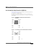
Step 2 If your ground wire is insulated, use a wire stripping tool to strip the 6-gauge
ground wire to 0.5 inch (12.7 mm) ± 0.02 inch (0.5 mm), as shown in Figure C-1.
Figure C-1 Stripping the Ground Wire
Step 3
Slide the open end of the ground lug over the exposed area of the 6-gauge wire.
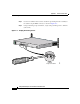
Step 4 Using a Panduit crimping tool, crimp the ground lug to the 6-gauge wire, as shown
in Figure C-2.
Figure C-2 Crimping the Ground Lug
Insulation
Wire lead
0.5 in. (12.7 mm)
±
0.02 in. (0.5 mm)
60528
60529