
Installation guide


Appendix C DC Power Connections
Connecting to DC Power
C-2
Catalyst 3550 Multilayer Switch Hardware Installation Guide
78-11358-06
Preparing for Installation
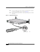
Locate the ground lug and the two number-10-32 screws on the switch rear panel
and the DC terminal block plug in the DC-switch accessory kit.
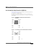
Obtain these necessary tools and equipment:
• Ratcheting torque screwdriver with a Phillips head that exerts up to
15 pound-force inches (lbf-in.) or 240 ounce-force inches (ozf-in.) of
pressure
• Panduit crimping tool with optional controlled cycle mechanism
(model CT-700, CT-720, CT-920, CT-920CH, CT-930, or CT-940CH)
• 6-gauge copper ground wire (insulated or noninsulated)
• Four leads of 18-gauge copper wire
• Wire-stripping tools for stripping 6- and 18-gauge wires
Grounding the Switch
Warning
This equipment is intended to be grounded. Ensure that the host is connected to
earth ground during normal use.
Caution To make sure that the equipment is reliably connected to earth ground, follow the
grounding procedure instructions, and use a UL-listed lug suitable for number-6
AWG wire and two number-10-32 ground-lug screws.
Warning
When installing the unit, always make the ground connection first and
disconnect it last.