
Installation guide


B-5
Catalyst 3550 Multilayer Switch Hardware Installation Guide
78-11358-06
Appendix B Connector and Cable Specifications
Cable and Adapter Specifications
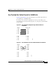
Four Twisted-Pair Cable Pinouts for 10/100 Ports
Figure B-6 and Figure B-7 show the schematics of four twisted-pair cables for
ports running 10 or 100 Mbps traffic.
For inline power connections, signal pairs are used to provide inline power.
Nominally, there is 48 V between the pin pairs (1–2), and pairs (3–6) when inline
power is active.
Figure B-6 Four Twisted-Pair Straight-Through Cable Schematic for
10/100 Ports
Figure B-7 Four Twisted-Pair Crossover Cable Schematic for 10/100 Ports
1 RD+
2 RD-
3TD+
6TD-
1TD+
Switch Router or PC
2TD-
3 RD+
6 RD-
4NC
5NC
7NC
8NC
4NC
5NC
7NC
8NC
65271
1 RD+
2 RD-
3TD+
6TD-
1 RD+
Switch Switch
2 RD-
3 TD+
6 TD-
4NC
5NC
7NC
8NC
4NC
5NC
7NC
8NC
65273