
Installation guide


Chapter 1 Overview
Rear-Panel Description
1-12
Catalyst 2950 Desktop Switch Hardware Installation Guide
78-11157-01
Rear-Panel Description
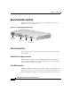
The switch rear panel has an AC power connector, an RPS connector, and an
RJ-45 console port. (See Figure 1-9.)
Figure 1-9 Catalyst 2950 Switch Rear Panel
Power Connectors
You can provide power to a switch either by using the internal power supply or
the Cisco RPS.
Internal Power Supply Connector
The internal power supply is an autoranging unit that supports input voltages
between 100 and 240 VAC. Use the supplied AC power cord to connect the AC
power connector to an AC power outlet.
Cisco RPS Connector
The RPS is a 300W redundant power system that can support six external network
devices and provides power to one failed device at a time. It automatically senses
when the internal power supply of a connected device fails and provides power to
RATING
100-127V~
@ 1A
200-240V~
@0.5A
50-60Hz
DC INPUT FOR REMOTE
POWER SUPPLY
SPECIFIED IN MANUAL.
+12V @4.5A
CONSOLE
AC power
connector
RPS
connector
Fan
RJ-45
console port
45585