C H A P T E R 1 Overview This chapter provides information about the following topics: • Switch features • Front- and rear-panel descriptions • Management options Features The Catalyst 2950 series switches are stackable Ethernet switches to which you can connect workstations and other network devices, such as servers, routers, and other switches. The switches can be deployed as backbone switches, aggregating 10BASE-T, 100BASE-TX, and Gigabit Ethernet traffic from other network devices.
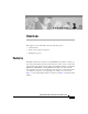
Chapter 1 Overview Features Catalyst 2950 Series Switches Version Number Description WS-C2950-12 12 fixed autosensing 10/100 ports Switch SYST RPS STAT UTIL DUPLX 1x 2x 3x 4x 5x SPEED 6x 7x 8x MODE WS-C2950-24 24 fixed autosensing 10/100 ports SYST RPS STAT UTIL DUPLX 1x 2x 3x 4x 5x SPEED 6x 7x 8x MODE WS-C2950C-24 24 fixed autosensing 10/100 ports 2 100BASE-FX ports SYST RPS STAT UTIL DUPLX 1x 2x 3x 4x 5x SPEED 6x 7x 8x MODE 9x 9x 9x 10x 10x 10x 11x 1
Chapter 1 Overview Front-Panel Description Table 1-1 Catalyst 2950 Switch Features Feature Hardware Configuration Power redundancy Description • 12 10/100 Ethernet ports • 24 10/100 Ethernet ports • 24 10/100 Ethernet ports and 2 100BASE-FX ports • 24 10/100 Ethernet ports and 2 10/100/1000 Ethernet ports • Autonegotiates the speed and duplex settings on 10/100 ports and on 10/100/1000 ports • Autonegotiates the duplex setting on 100BASE-FX ports • Supports 8192 MAC addresses • Checks
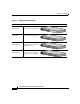
Chapter 1 Overview Front-Panel Description SYST RPS STAT UTIL DUPLX 1x 2x Catalyst 2950-12 Switch 3x 4x 5x SPEED 6x 7x 8x MODE 9x 10x 10Base-T 11x / 100Base- TX 12x Catalyst 295 0 SERIES 45568 Figure 1-2 10/100 ports SYST RPS STAT UTIL DUPLX 1 2 Catalyst 2950-24 Switch 3 4x 5x SPEED 6x 7x 8x MODE 9x 10x 10Base-T 11x / 100Base- TX 12x 13x 14x 15x 16x 17x 18x 19x 20x Catalyst 295 21x 0 SERIES 22x 23x 45567 Figure 1-3 24x 10/100 ports SYST RPS STAT
Chapter 1 Overview Front-Panel Description SYST RPS STAT UTIL DUPLX 1x 2x Catalyst 2950T-24 Switch 3x SPEED 4x 5x 6x 7x MODE 8x 9x 10x 10Base-T 11x / 100Base- TX 12x 13x 14x 15x 16x 17x 18x 19x 20x Catalyst 295 21x 0 SERIES 22x 23x 24x 10/100/1 47337 Figure 1-5 00Base-T 1 2 10/100 ports 10/100/1000 ports 10/100 Ports The 10/100 ports use RJ-45 connectors and Category 5 cabling.
Chapter 1 Overview Front-Panel Description Table 1-2 MT-RJ Patch Cables Type Cisco Part Number 1-meter, MT-RJ-to-SC multimode cable CAB-MTRJ-SC-MM-1M 3-meter, MT-RJ-to-SC multimode cable CAB-MTRJ-SC-MM-3M 5-meter, MT-RJ-to-SC multimode cable CAB-MTRJ-SC-MM-5M 1-meter, MT-RJ-to-ST multimode cable CAB-MTRJ-ST-MM-1M 3-meter, MT-RJ-to-ST multimode cable CAB-MTRJ-ST-MM-3M 5-meter, MT-RJ-to-ST multimode cable CAB-MTRJ-ST-MM-5M 10/100/1000 Ports The 10/100/1000 ports use RJ-45 connectors and Cat
Chapter 1 Overview Front-Panel Description Figure 1-6 LEDs RPS LED Port status LEDs System LED SYST RPS Port mode LEDs STAT UTIL D UPLX 1x 2x 3x SPEED 4x 5x 6x MODE 52918 Mode button System LED The system LED shows whether the system is receiving power and functioning properly. Table 1-3 lists the LED colors and meanings. Table 1-3 System LED Color System Status Off System is not powered up. Green System is operating normally.
Chapter 1 Overview Front-Panel Description RPS LED The RPS LED shows the RPS status. Table 1-4 lists the LED colors and meanings. Table 1-4 RPS LED Color RPS Status Off RPS is off or is not installed. Solid green RPS is connected and operational. Blinking green RPS is backing up another switch in the stack. Solid amber RPS is connected but not functioning properly. • RPS could be in standby mode.
Chapter 1 Overview Front-Panel Description Table 1-5 Port Mode LEDs Mode LED Port Mode Description STAT Port status The port status. This mode is the default mode. UTIL Switch utilization The current bandwidth in use by the switch. DUPLX Port duplex mode The port duplex mode: half duplex or full duplex. SPEED Port speed The port operating speed: 10 or 100 Mbps for 10/100 ports and 10, 100, or 1000 Mbps for 10/100/1000 ports.
Chapter 1 Overview Front-Panel Description When you change the port mode, the meaning of the port LED colors changes. Table 1-6 explains how to interpret the port LED colors. Table 1-6 Meaning of Port LED Colors in Different Modes Port Mode Color Meaning STAT (port status) Off No link. Solid green Link present. Flashing green Activity. Port is transmitting or receiving data. Alternating green-amber Link fault.
Chapter 1 Overview Front-Panel Description Table 1-6 Meaning of Port LED Colors in Different Modes (continued) Port Mode Color Meaning SPEED (speed) 10/100 ports Off Port is operating at 10 Mbps. Green Port is operating at 100 Mbps. 10/100/1000 ports Off Port is operating at 10 Mbps. Green Port is operating at 100 Mbps. Flashing green Port is operating at 1000 Mbps. Figure 1-8 shows the bandwidth utilization percentages displayed by the right-most LEDs.
Chapter 1 Overview Rear-Panel Description Rear-Panel Description The switch rear panel has an AC power connector, an RPS connector, and an RJ-45 console port. (See Figure 1-9.) RATING 100-127V~ @ 1A 200-240V~ @0.5A 50-60Hz Catalyst 2950 Switch Rear Panel DC INPUT FO POWE R REMOTE SPECIF R SUPPLY IED IN +12V @4MANUAL. .
Chapter 1 Overview Management Options the failed device, preventing loss of network traffic. When the internal power supply has been brought up or replaced, the RPS automatically stops powering the device. Warning Attach only the Cisco RPS 300 (model PWR300-AC-RPS-N1) to the RPS receptacle. For more information about the Cisco RPS 300, refer to the Cisco RPS 300 Redundant Power System Hardware Installation Guide.
Chapter 1 Overview Management Options • CiscoView application You can use the CiscoView device-management application to set configuration parameters and to view switch status and performance information. This application, which you purchase separately, can be a standalone application or part of an Simple Network Management Protocol (SNMP) network-management platform. For more information, refer to the documentation that came with your CiscoView application.