
Troubleshooting guide


1-11
Cisco Wide Area Application Services Configuration Guide
OL-26579-01
Chapter 1 Configuring AppNav
Configuring an AppNav Cluster
3. (Optional) Configure AppNav class maps. This step is necessary only if you want to customize the
default class map configuration. The system adds several default class maps that match traffic
corresponding to most of the application accelerators and a class-default class map that matches all
traffic. See the “Configuring AppNav Class Maps” section on page 1-19.
4. (Optional) Configure an AppNav policy. This step is necessary only if you want to customize the
default policy. The system adds a default policy that distributes all traffic to the WNG-Default
WNG, which is the node group into which all WNs are grouped by default. See the “Configuring
Rules Within an AppNav Policy” section on page 1-22.
5. (Optional) Configure WAAS node optimization class maps and policy rules. This step is necessary
only if you want to customize the default optimization policy that is listed in Appendix 1,
“Predefined Optimization Policy.”
6. (Optional) Configure an interception ACL on the ANCs. See the “Configuring AppNav Controller
ACLs” section on page 1-26.
Configuring WAAS Device Interfaces
Before you can use the AppNav Cluster wizard to create an AppNav Cluster, you must connect the
WAAS device interfaces and configure the management interfaces. Configuration differs depending on
whether management traffic uses a separate interface or shares the traffic handling interface.
This section contains the following topics:
• Interface Configuration with a Separate Management Interface, page 1-11
• Interface Configuration with a Shared Management Interface, page 1-12
• Interface Configuration Considerations, page 1-13
For more information about device interface configuration, see Chapter 1, “Configuring Network
Settings.” For more information about configuring a bridge group for inline interception mode, see the
“Configuring Inline Operation on ANCs” section on page 1-49.
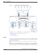
Interface Configuration with a Separate Management Interface
If you want management traffic to use a dedicated interface, separate from the traffic data path, connect
and configure the devices as described in this section.
AppNav Controller
Step 1 Connect the last AppNav Controller Interface Module port to the switch/router port for the cluster traffic.
For example, this port is GigabitEthernet 1/11 on a 12-port module or TenGigabitEthernet 1/3 on a 4-port
module.
Step 2 Connect a built-in Ethernet port to the switch/router port for the management interface.
Step 3 For an in-path (inline) deployment, connect the first pair of ports on the AppNav Controller Interface
Module (for example, GigabitEthernet 1/0 [LAN] and GigabitEthernet 1/1 [WAN] for bridge 1) to
corresponding switch/router ports.
If the ANC is connected to a second router for a dual inline deployment, connect the second pair of ports
on the AppNav Controller Interface Module (for example, GigabitEthernet 1/2 [LAN] and
GigabitEthernet 1/3 [WAN] for bridge 2) to corresponding switch/router ports.
Step 4 Use the device setup command to configure the following settings: