
Troubleshooting guide

1-5
Cisco Wide Area Application Services Configuration Guide
OL-26579-01
Chapter 1 Configuring Network Settings
Configuring Network Interfaces
Step 12 In the Assign Interfaces area, check the boxes next to the two interfaces that you want to assign to this
standby group and click the Assign taskbar icon. To unassign any assigned interfaces, check each
interface that you want to unassign and click the Unassign taskbar icon.
If you want to have two port-channel interfaces as members of the standby group, do not assign any
interfaces here. When you create the port-channel interfaces, you assign the standby group number in
that window.
Step 13 To assign one physical interface as the primary (active) interface in the standby group, ensure that it is
the only interface checked and then click the Enable Primary taskbar icon.
Step 14 Click OK.
Configuring a Standby Interface on a Device Earlier than Version 5.0
To configure a standby interface for devices with WAAS versions earlier than 5.0, follow these steps:
Step 1 From the WAAS Central Manager menu, choose Devices > device-name.
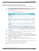
Step 2 Choose Configure > Network > Network Interfaces. The Network Interfaces window for the device
appears.
Step 3 In the taskbar, click the Create New Interface icon. The Creating New Network Interface window
appears.
Step 4 From the Port Type drop-down list, choose Standby. The window refreshes with fields for configuring
the standby group settings.
Step 5 From the Standby Group Number drop-down list, choose a group number for the interface.
Step 6 (Optional) In the Description field, optionally enter a description for the standby group.
Step 7 In the Address field, specify the IP address of the standby group.
Step 8 In the Netmask field, specify the netmask of the standby group.
Step 9 (Optional) Check the Shutdown check box to shut down the hardware interface. By default, this option
is disabled.
Step 10 In the Default Gateway field, enter the default gateway IP address. If an interface is configured for
DHCP, then this field is read only.
Step 11 (Optional) From the Bridge Group Number drop-down list, choose a bridge virtual interface (BVI) group
number with which to associate this standby interface, or choose None. For more information on BVI,
see the “Bridging to a Virtual Blade Interface” section on page 1-17.
Step 12 Click Submit.
Step 13 Configure the physical interface members as described in the “Assigning Physical Interfaces to the
Standby Group” section on page 1-5.
After you create the standby interface, you need to assign two physical interfaces to the standby group.