
Troubleshooting guide


1-53
Cisco Wide Area Application Services Configuration Guide
OL-26579-01
Chapter 1 Configuring Traffic Interception
Using Inline Mode Interception
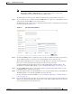
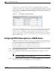
Step 5 Click Submit.
This facility for creating VLAN lists is provided so that you can configure VLAN lists globally. You do
not need to use this facility to configure VLANs for an inline interface. You can configure VLANs
directly in the inline interface settings window, as described in the “Configuring Inline Interface Settings
on WAEs” section on page 1-46.
Information About Clustering Inline WAEs
You can serially cluster two WAE devices that are operating in inline mode to provide higher availability
in the data center if a device fails. If the current optimizing device fails, the inline group shuts down, or
the device becomes overloaded, the second WAE device in the cluster provides the optimization services.
Deploying WAE devices in a serial inline cluster for scaling or load balancing is not supported.
Note Overload failover occurs on TFO overload, not overload of individual application accelerators, and it is
intended for temporary overload protection. We do not recommend that you continually run a WAE in
an overloaded state, frequently triggering overload failover.
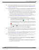
A serial cluster consists of two WAE devices connected together sequentially in the traffic path. The
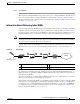
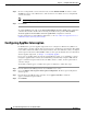
WAN port of one device is connected to the LAN port of the next device, as shown in Figure 1-9.
Figure 1-9 Inline Cluster
In a serial cluster, all traffic between the switch and router passes through all inline WAEs. In Figure 1-9,
TCP connections are optimized by WAE-1. If WAE-1 fails, it bypasses the traffic and connections are
then optimized by WAE-2.
The policy configuration of serially clustered WAEs should be the same. Additionally, we recommend
that you use the same device for both WAEs in the cluster.
When serially clustering inline WAEs, on each WAE you must configure the address of the other WAE
in the cluster as a non-optimizing peer. This disables optimization between the two peer WAEs in the
serial cluster, since you want optimization only between the WAE peers on each side of the WAN link.
For information on how to disable optimization between peers, see the “Disabling Peer Optimization
Between Serial Inline WAEs” section on page 1-54.
1 Inline LAN port on WAE-1 3 Inline LAN port on WAE-2
2 Inline WAN port on WAE-1 4 Inline WAN port on WAE-2
1 2
159918
3 4
File and
application servers
Switch
WAE-1 WAE-2
Router
WAN