
Troubleshooting guide


1-52
Cisco Wide Area Application Services Configuration Guide
OL-26579-01
Chapter 1 Configuring Traffic Interception
Using Inline Mode Interception
The inline adapter supports only a single VLAN ID for each inline group interface. If you have
configured a secondary address from a different subnet on an inline interface, you must have the same
secondary address assigned on the router subinterface for the VLAN.
Using IEEE 802.1Q tunneling increases the frame size by 4 bytes when the tag is added. Therefore, you
must configure all switches through which the tunneled packet traverses to be able to process larger
frames by increasing the device MTU to at least 1504 bytes.
The following operating considerations apply to configuring IP addresses on the inline interfaces:
• This feature provides basic routable interface support and does not support the following additional
features associated with the built-in interfaces: standby and port channel.
• If you have configured a WAE to use the inline interfaces for all traffic, inline interception must be
enabled or the WAE will not receive any traffic.
• If you have configured a WAE to use the inline interfaces for all traffic and it goes into mechanical
bypass mode, the WAE become inaccessible through the inline interface IP address. Console access
is required for device management when an inline interface is in bypass mode.
• If you have configured a WAE with an IP address on an inline interface, the interface can accept only
traffic addressed to it and ARP broadcasts, and the interface cannot accept multicast traffic.
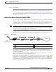
• In a deployment using the Hot Standby Router Protocol (HSRP) where two routers that participate
in an HSRP group are directly connected through two inline groups, HSRP works for all clients if
the active router fails. However, this redundancy does not apply to the IP address of the WAE itself
for management traffic, if management traffic is also configured to use the inline interface. If the
active router fails, you will not be able to connect to the WAE inline IP address because the inline
interface is physically connected to the failed router interface. You will be able to connect to the
WAE through the second inline group interface that is connected to the standby router. If redundancy
is needed for the IP address of the WAE itself for management traffic, we recommend that you use
the IP addresses of the built-in interfaces rather than the inline interfaces.
Configuring VLANs for Inline Support
Initially, the WAE accepts traffic from all VLANs. You can configure the WAE to include or exclude
traffic from certain VLANs; for excluded VLANs, traffic is bridged across the LAN/WAN interfaces in
a group and is not processed.
To configure a VLAN for inline support, follow these steps:
Step 1 From the WAAS Central Manager menu, choose Configure > Platform > Vlans.
The Vlans window appears, which lists the VLANs that are defined. You can click the Edit Vlan icon
next to an existing VLAN that you want to modify.
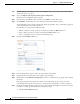
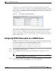
Step 2 In the taskbar, click the Create New Vlan icon. The Creating VLAN window appears.
Step 3 In the VLAN Name field, enter a name for the VLAN list.
Step 4 In the VLAN Ranges field, enter a list of one or more VLAN ranges. Separate each VLAN range from
the next with a comma (but no space). This list of VLAN ranges can be included or excluded from
optimization when you configure the inline interface group, as described in the “Configuring Inline
Interface Settings on WAEs” section on page 1-46. You cannot specify the term “native” in this field.