
Troubleshooting guide


1-34
Cisco Wide Area Application Services Configuration Guide
OL-26579-01
Chapter 1 Configuring Traffic Interception
Using Policy-Based Routing Interception
You can enable PBR to establish a route that goes through WAAS for some or all packets. WAAS proxy
applications receive PBR-redirected traffic in the same manner as WCCP redirected traffic, as follows:
1. In the branch office, define traffic of interest on the branch office router (Edge-Router1) as follows:
a. Specify which traffic is of interest to the LAN interface (ingress interface) on Edge-Router1.
Use extended IP access lists to define traffic of interest (traffic from all or filtered local source
addresses to any or filtered destination address).
b. Specify which traffic is of interest to the WAN interface (egress interface) on Edge-Router1.
Use extended IP access lists to define traffic of interest (traffic from all or filtered local source
addresses from any or filtered remote addresses).
2. In the data center, specify which traffic is of interest to the data center router (Core-Router1) as
follows:
a. Specify which traffic is of interest to the LAN interface (ingress interface) on Core-Router1.
Use extended IP access lists to define traffic of interest (traffic from all or filtered local source
addresses to any or filtered destination address).
b. Specify which traffic is of interest to the WAN interface (egress interface) on Core-Router1.
Use extended IP access lists to define traffic of interest (traffic from all or filtered local source
addresses from any or filtered remote addresses).
3. In the branch office, create route maps on Edge-Router1, as follows:
a. Create a PBR route map on the LAN interface of Edge-Router1.
b. Create a PBR route map on the WAN interface of Edge-Router1.
4. In the data center, create route maps on Core-Router1, as follows:
a. Create a PBR route map on the LAN interface of Core-Router1.
b. Create a PBR route map on the WAN interface of Core-Router1.
5. In the branch office, apply the PBR route maps to Edge-Router1.
6. In the data center, apply the PBR route maps to Core-Router1.
7. Determine which PBR method to use to verify PBR next-hop availability of a WAE. For more
information, see the “Methods of Verifying PBR Next-Hop Availability” section on page 1-39.
Note For a description of the PBR commands that are referenced in this section, see the Cisco Quality of
Service Solutions Command Reference.
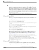
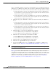
Figure 1-5 shows that the WAEs (Edge-WAE1 and Core-WAE1) must reside in an out-of-band network
that is separate from the traffic’s destination and source. For example, Edge-WAE1 is on a subnet
separate from the clients (the traffic source), and Core-WAE is on a subnet separate from the file servers
and application servers (the traffic destination). Additionally, the WAE may need to be connected to the
router that is redirecting traffic to it through a tertiary interface (a separate physical interface) or
subinterface to avoid a routing loop. For more information on this topic, see the “Using Tertiary
Interfaces or Subinterfaces to Connect WAEs to Routers” section on page 1-24.