
Troubleshooting guide


1-33
Cisco Wide Area Application Services Configuration Guide
OL-26579-01
Chapter 1 Configuring AppNav
Configuring an AppNav Cluster
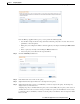
Step 6 Configure the WNG and interfaces for each WN device you are adding.
a. From the WAAS Node Group drop-down list, choose the WNG to which you want to add the new
WNs. The list shows defined WNGs.
b. Click Next.
c. Use the Cluster Interface Wizard graphical interface to configure the WN interfaces. For details on
using this wizard, see the “Configuring Interfaces with the Graphical Interface Wizard” section on
page 1-17.
d. From the Cluster Interface drop-down list, select the interface to be used for intra-cluster traffic.
e. (Optional) To enable swapping of client and WAAS device source IP address fields in intra-cluster
traffic, check the Enable swapping of source IP address in intra-cluster traffic check box.
You may want to enable this option if you are using a port channel for the cluster interface or there
is a load balancing device between the ANC and WN. This option may improve the load balancing
of traffic that the ANC distributes to WNs for optimization because it load balances based on the
client IP address rather than the ANC IP address. (For traffic from the server to the client, it swaps
the server IP address with the ANC IP address.) The Central Manager enables this feature
automatically if any existing ANCs have port channel cluster interfaces.
f. Click Next to save the settings and continue with the next WN you are adding. If this is the last WN
being added, click Finish.
Step 7 Configure and enable optimization on the WNs. For details on configuring optimization, see Chapter 1,
“Configuring Application Acceleration.”
After a convergence waiting period of up to two minutes, the new WNs are available on all the ANCs
for optimization.
Removing a WAAS Node from a Cluster
To remove a WAAS node (WN) from a cluster, follow these steps:
Step 1 From the WAAS Central Manager menu, choose AppNav Clusters > cluster-name.
Step 2 Click the WA A S N o d e s tab below the topology diagram.
Step 3 Choose the node and click the Disable taskbar icon.
This causes a graceful exit of the WN from the cluster, where the ANCs stop sending new flows to the
WN but continue to distribute existing flows to it until the connection count reaches zero or the
maximum shutdown wait time expires.
Note The default shutdown wait time is 120 seconds. You can configure it from the Shutdown Wait
Time field in the AppNav Cluster tab.
Step 4 (Optional) When the graceful exit process on the WN is complete (all existing connections have
terminated), remove the WN from the WNG on the ANCs by choosing the node and clicking the Delete
taskbar icon.
You can monitor the node status in the topology diagram in the upper part of the window. The colored
status light indicator on the device turns gray when the node is no longer processing connections.