
Getting Started Guide
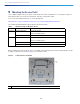
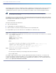

Table Of Contents
- Cisco Catalyst 9120AX Series Access Points
- 1 About this Guide
- 2 About the Access Point
- 3 Safety Instructions
- 4 Unpacking
- 5 AP Views, Ports, and Connectors
- 6 Preparing the AP for Installation
- 7 Installation Overview
- 8 Performing a Pre-Installation Configuration
- 9 Mounting the Access Point
- 10 Powering the Access Point
- 11 Configuring and Deploying the Access Point
- 12 Checking the Access Point LEDs
- 13 Miscellaneous Usage and Configuration Guidelines
- 14 FAQs
- 15 Related Documentation
- 16 Declarations of Conformity and Regulatory Information
- Manufacturers Federal Communication Commission Declaration of Conformity Statement
- VCCI Statement for Japan
- Guidelines for Operating Cisco Catalyst Access Points in Japan
- Statement 371—Power Cable and AC Adapter
- Industry Canada
- Canadian Compliance Statement
- European Community, Switzerland, Norway, Iceland, and Liechtenstein
- Declaration of Conformity for RF Exposure
- Generic Discussion on RF Exposure
- This Device Meets International Guidelines for Exposure to Radio Waves
- This Device Meets FCC Guidelines for Exposure to Radio Waves
- This Device Meets the Industry Canada Guidelines for Exposure to Radio Waves
- Cet appareil est conforme aux directives internationales en matière d'exposition aux fréquences radioélectriques
- Additional Information on RF Exposure
- Administrative Rules for Cisco Catalyst Access Points in Taiwan
- Operation of Cisco Catalyst Access Points in Brazil
- Declaration of Conformity Statements
- Communications, Services, and Additional Information
- Cisco Bug Search Tool

15
Cisco Catalyst 9120AX Series Access Points
12 Checking the Access Point LEDs
The location of the access point status LED is shown in Figure 2.
Note Regarding LED status colors, it is expected that there will be small variations in color intensity and hue from
unit to unit. This is within the normal range of the LED manufacturer’s specifications and is not a defect.
However, the intensity of the LED can be changed through the controller.
The access point status LED indicates various conditions and are described in Table 2.
Table 2 LED Status Indications
Message Type LED State Message Meaning
Association status Green Normal operating condition, but no
wireless client associated
Blue Normal operating condition, at least one
wireless client association
Boot loader status Green Executing boot loader
Boot loader error Blinking Green Boot loader signing verification failure
Operating status Blinking Blue Software upgrade in progress
Alternating between Green and
Red
Discovery/join process in progress
Cycling through
Red-Off-Green-Off-Blue-Off
Access point location command invoked
from controller web interface.
Access point operating
system errors
Cycling through
Blue-Red-Green-Off
General warning; insufficient inline power