
Getting Started Guide
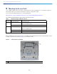

Table Of Contents
- Cisco Catalyst 9120AX Series Access Points
- 1 About this Guide
- 2 About the Access Point
- 3 Safety Instructions
- 4 Unpacking
- 5 AP Views, Ports, and Connectors
- 6 Preparing the AP for Installation
- 7 Installation Overview
- 8 Performing a Pre-Installation Configuration
- 9 Mounting the Access Point
- 10 Powering the Access Point
- 11 Configuring and Deploying the Access Point
- 12 Checking the Access Point LEDs
- 13 Miscellaneous Usage and Configuration Guidelines
- 14 FAQs
- 15 Related Documentation
- 16 Declarations of Conformity and Regulatory Information
- Manufacturers Federal Communication Commission Declaration of Conformity Statement
- VCCI Statement for Japan
- Guidelines for Operating Cisco Catalyst Access Points in Japan
- Statement 371—Power Cable and AC Adapter
- Industry Canada
- Canadian Compliance Statement
- European Community, Switzerland, Norway, Iceland, and Liechtenstein
- Declaration of Conformity for RF Exposure
- Generic Discussion on RF Exposure
- This Device Meets International Guidelines for Exposure to Radio Waves
- This Device Meets FCC Guidelines for Exposure to Radio Waves
- This Device Meets the Industry Canada Guidelines for Exposure to Radio Waves
- Cet appareil est conforme aux directives internationales en matière d'exposition aux fréquences radioélectriques
- Additional Information on RF Exposure
- Administrative Rules for Cisco Catalyst Access Points in Taiwan
- Operation of Cisco Catalyst Access Points in Brazil
- Declaration of Conformity Statements
- Communications, Services, and Additional Information
- Cisco Bug Search Tool

14
Cisco Catalyst 9120AX Series Access Points
Access points must be discovered by a controller before they can become an active part of the network. The access
point supports these controller discovery processes:
Layer 3 CAPWAP discovery—Can occur on different subnets than the access point and uses IP addresses and UDP
packets rather than MAC addresses used by Layer 2 discovery.
Locally stored controller IP address discovery—If the access point was previously joined to a controller, the IP
addresses of the primary, secondary, and tertiary controllers are stored in the access point non-volatile memory. This
process of storing controller IP addresses on an access point for later deployment is called priming the access point.
For more information about priming, see the “Performing a Pre-Installation Configuration” section on page 10.
DHCP server discovery—This feature uses DHCP option 43 to provide controller IP addresses to the access points.
Cisco switches support a DHCP server option that is typically used for this capability. For more information about
DHCP option 43, see the “Configuring DHCP Option 43” section on page 17.
DNS discovery—The access point can discover controllers through your domain name server (DNS). For the access
point to do so, you must configure your DNS to return controller IP addresses in response to
CISCO-CAPWAP-CONTROLLER.localdomain, where localdomain is the access point domain name. Configuring the
CISCO-CAPWAP-CONTROLLER provides backwards compatibility in an existing customer deployment. When an
access point receives an IP address and DNS information from a DHCP server, it contacts the DNS to resolve
CISCO-CAPWAP-CONTROLLER.localdomain. When the DNS sends a list of controller IP addresses, the access
point sends discovery requests to the controllers.
Deploying the Access Point on the Wireless Network
After you have mounted the access point, follow these steps to deploy it on the wireless network:
Step 1 Connect and power up the access point.
Step 2 Observe the access point LED (for LED descriptions, see “Checking the Access Point LEDs” section on
page 15).
a. When you power up the access point, it begins a power-up sequence that you can verify by observing the
access point LED. If the power-up sequence is successful, the discovery and join process begins. During this
process, the LED blinks sequentially green, red, and off. When the access point has joined a controller, the
LED is chirping green if no clients are associated or green if one or more clients are associated.
b. If the LED is not on, the access point is most likely not receiving power.
c. If the LED blinks sequentially for more than 5 minutes, the access point is unable to find its primary,
secondary, and tertiary Cisco wireless LAN controller. Check the connection between the access point and the
Cisco wireless LAN controller, and be sure the access point and the Cisco wireless LAN controller are either
on the same subnet or that the access point has a route back to its primary, secondary, and tertiary Cisco
wireless LAN controller. Also, if the access point is not on the same subnet as the Cisco wireless LAN
controller, be sure that there is a properly configured DHCP server on the same subnet as the access point.
See the “Configuring DHCP Option 43” section on page 17 for additional information.
Step 3 Reconfigure the Cisco wireless LAN controller so that it is not the Master.
Note A Master Cisco wireless LAN controller should be used only for configuring access points and not
in a working network.