
Getting Started Guide
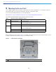
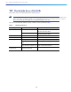

Table Of Contents
- Cisco Catalyst 9120AX Series Access Points
- 1 About this Guide
- 2 About the Access Point
- 3 Safety Instructions
- 4 Unpacking
- 5 AP Views, Ports, and Connectors
- 6 Preparing the AP for Installation
- 7 Installation Overview
- 8 Performing a Pre-Installation Configuration
- 9 Mounting the Access Point
- 10 Powering the Access Point
- 11 Configuring and Deploying the Access Point
- 12 Checking the Access Point LEDs
- 13 Miscellaneous Usage and Configuration Guidelines
- 14 FAQs
- 15 Related Documentation
- 16 Declarations of Conformity and Regulatory Information
- Manufacturers Federal Communication Commission Declaration of Conformity Statement
- VCCI Statement for Japan
- Guidelines for Operating Cisco Catalyst Access Points in Japan
- Statement 371—Power Cable and AC Adapter
- Industry Canada
- Canadian Compliance Statement
- European Community, Switzerland, Norway, Iceland, and Liechtenstein
- Declaration of Conformity for RF Exposure
- Generic Discussion on RF Exposure
- This Device Meets International Guidelines for Exposure to Radio Waves
- This Device Meets FCC Guidelines for Exposure to Radio Waves
- This Device Meets the Industry Canada Guidelines for Exposure to Radio Waves
- Cet appareil est conforme aux directives internationales en matière d'exposition aux fréquences radioélectriques
- Additional Information on RF Exposure
- Administrative Rules for Cisco Catalyst Access Points in Taiwan
- Operation of Cisco Catalyst Access Points in Brazil
- Declaration of Conformity Statements
- Communications, Services, and Additional Information
- Cisco Bug Search Tool

12
Cisco Catalyst 9120AX Series Access Points
9 Mounting the Access Point
Cisco Catalyst 9120AX series access points can be mounted in several configurations – on a suspended ceiling, on a
hard ceiling or wall, on an electrical or network box, and above a suspended ceiling.
For access point mounting instructions, go to the following URL:
http://www.cisco.com/c/en/us/td/docs/wireless/access_point/mounting/guide/apmount.html
The standard mounting hardware supported by the AP is listed in Table 1.
When mounting the AP in areas where there is a possibility of the AP being knocked off the mounting bracket, use the
lock hasp on the back of the AP (see Figure 4) to lock it to the bracket.
Figure 4 Locking the AP to the Bracket
Table 1 Brackets and Clips for Mounting the AP
Part Number Description
Brackets
1
1. Mount the AP using no less than four screw holes on a bracket.
AIR-AP-BRACKET-1 Low-profile bracket
(This is the default option)
AIR-AP-BRACKET-2 Universal bracket
Clips AIR-AP-T-RAIL-R Ceiling Grid Clip (Recessed mounting)
(This is the default option)
AIR-AP-T-RAIL-F Ceiling Grid Clip (Flush mounting)
AIR-CHNL-ADAPTER Optional adapter for channel-rail ceiling grid profile.
1
Position of the hasps for the locks on the back of the 9120AXI model