Spec Sheet Cisco UCS C220 M4 High-Density Rack Server (Large Form Factor Disk Drive Model) CISCO SYSTEMS 170 WEST TASMAN DR SAN JOSE, CA, 95134 WWW.CISCO.COM PUBLICATION HISTORY REV B.
CONTENTS OVERVIEW . . . . . . . . . . . . . . . . . . . . . . . . . . . . . . . . . . . . . . . . . . . . . . . 3 DETAILED VIEWS . . . . . . . . . . . . . . . . . . . . . . . . . . . . . . . . . . . . . . . . . . . 4 Chassis Front View . . . . . . . . . . . . . . . . . . . . . . . . . . . . . . . . . . . . . . . . . . . . . . . . . . .4 Chassis Rear View . . . . . . . . . . . . . . . . . . . . . . . . . . . . . . . . . . . . . . . . . . . . . . . . . . .5 BASE SERVER STANDARD CAPABILITIES and FEATURES . .
CONTENTS Motherboard USB and SD Ports, and RAID Card Backup Location . . . . . . . . . . . . . . . . . . . . 70 TECHNICAL SPECIFICATIONS . . . . . . . . . . . . . . . . . . . . . . . . . . . . . . . . . . 71 Dimensions and Weight . . . . . . . . . . . . . . . . . . . . . . . Power Specifications . . . . . . . . . . . . . . . . . . . . . . . . Environmental Specifications . . . . . . . . . . . . . . . . . . . Compliance Requirements . . . . . . . . . . . . . . . . . . . . . 3 .... .... .... .... ... ...
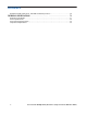
Cisco UCS C220 M4 High-Density Rack Server (Large Form Factor Disk Drive Model)
OVERVIEW OVERVIEW The Cisco® UCS C220 M4 LFF rack server is the newest 2-socket, 1U rack server from Cisco, designed for both performance and expandability over a wide range of storage-intensive infrastructure workloads from big data to collaboration.
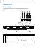
DETAILED VIEWS DETAILED VIEWS Chassis Front View Figure 2 shows the front view of the Cisco UCS C220 M4 High-Density LFF Rack Server. Chassis Front View 4 5 7 6 8 10 3 2 HDD 01 9 HDD 02 HDD 03 352974 Figure 2 HDD 04 1 11 1 Drives (up to four 3.
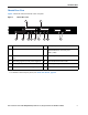
DETAILED VIEWS Chassis Rear View Figure 3 shows the external features of the rear panel.
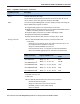
BASE SERVER STANDARD CAPABILITIES and FEATURES BASE SERVER STANDARD CAPABILITIES and FEATURES Table 1 lists the capabilities and features of the base server. Details about how to configure the server for a particular feature or capability (for example, number of processors, disk drives, or amount of memory) are provided in CONFIGURING the SERVER, page 10.
BASE SERVER STANDARD CAPABILITIES and FEATURES Table 1 Capabilities and Features (continued) Capability/Feature Description Cisco Flexible Flash drives The server supports up to two internal 32 GB or two internal 64 GB Cisco Flexible Flash drives (SD cards). The second SD card is blank and can be used to mirror the first SD card. It can be used to protect the Hypervisor Partition with RAID1.
BASE SERVER STANDARD CAPABILITIES and FEATURES Table 1 Capabilities and Features (continued) Capability/Feature Description Modular LAN on Motherboard (mLOM) slot The mLOM slot can flexibly accommodate the following cards: ■ Cisco Virtual Interface Cards (VIC) ■ Quad Port Intel i350 1GbE RJ45 Network Interface Card (NIC) NOTE: The four Intel i350 ports are provided on an optional card that plugs into the mLOM slot, and are separate from the two embedded (on the motherboard) LAN ports Interfaces ■
BASE SERVER STANDARD CAPABILITIES and FEATURES Table 1 Capabilities and Features (continued) Capability/Feature Description Integrated management processor Baseboard Management Controller (BMC) running Cisco Integrated Management Controller (CIMC) firmware. Depending on your CIMC settings, the CIMC can be accessed through the 1-GbE dedicated management port, the 1-GbE LOM ports, or a Cisco virtual interface card (VIC).
CONFIGURING the SERVER CONFIGURING the SERVER Follow these steps to configure the Cisco UCS C220 M4 High-Density LFF Rack Server: 10 ■ STEP 1 VERIFY SERVER SKU, page 11 ■ STEP 2 SELECT CPU(s), page 12 ■ STEP 3 SELECT MEMORY, page 14 ■ STEP 4 SELECT RAID CONTROLLERS, page 19 ■ STEP 5 SELECT HARD DISK DRIVES (HDDs), page 25 ■ STEP 6 SELECT PCIe OPTION CARD(s), page 26 ■ STEP 7 ORDER OPTIONAL NETWORK CARD ACCESSORIES, page 29 ■ STEP 8 ORDER POWER SUPPLY, page 33 ■ STEP 9 SELECT AC POWER COR
CONFIGURING the SERVER STEP 1 VERIFY SERVER SKU Verify the product ID (PID) of the server as shown in Table 2. Table 2 PID of the C220 M4 High-Density LFF Rack Base Server Product ID (PID) Description UCSC-C220-M4L UCS C220 M4 LFF, no CPU, memory, HDD, power supply, SD cards, PCIe cards, or tool-less rail kit The Cisco C220 M4 server: ■ Does not include power supply, CPU, memory, hard disk drives (HDDs), SD cards, rail kit, plug-in PCIe cards.
CONFIGURING the SERVER STEP 2 SELECT CPU(s) The standard CPU features are: ■ ■ ■ Intel Xeon E5-2600 v3 series processor family CPUs Intel C610 series chipset Cache size of up to 45 MB Select CPUs The available CPUs are listed in Table 3. Table 3 Available Intel CPUs: E5-2600 v3 Series Processor Family CPUs Intel Number Clock Freq (GHz) Power (W) Cache Size (MB) Cores QPI Highest DDR4 DIMM Clock Support (MHz)1 UCS-CPU-E52699D E5-2699 v3 2.30 145 45 18 9.
CONFIGURING the SERVER Approved Configurations (1) 1-CPU configurations: ■ Select any one CPU listed in Table 3 on page 12. (2) 2-CPU Configurations: ■ Select two identical CPUs from any one of the rows of Table 3 on page 12. Caveats ■ You can select either one processor or two identical processors. ■ The selection of 1 or 2 CPUs depends on the desired server functionality.
CONFIGURING the SERVER STEP 3 SELECT MEMORY The standard memory features are: ■ ■ Figure 4 14 DIMMs — Clock speed: 2133 MHz — Ranks per DIMM: 1, 2, or 4 — Operational voltage: 1.2 V — Registered ECC DDR4 DIMMs (RDIMMs) or load-reduced DIMMs (LRDIMMs) Memory is organized with four memory channels per CPU, with up to three DIMMs per channel, as shown in Figure 4.
CONFIGURING the SERVER Select DIMMs and Memory Mirroring Select the memory configuration and whether or not you want the memory mirroring option. The available memory DIMMs and mirroring option are listed in Table 4. NOTE: When memory mirroring is enabled, the memory subsystem simultaneously writes identical data to two channels. If a memory read from one of the channels returns incorrect data due to an uncorrectable memory error, the system automatically retrieves the data from the other channel.
CONFIGURING the SERVER (2) 1-CPU configuration with memory mirroring: ■ Total Number of DIMMs Select 2, 4, 8, or 12 identical DIMMs. The DIMMs will be placed by the factory as shown in the following table.
CONFIGURING the SERVER ■ Select the memory mirroring option (N01-MMIRROR) as shown in Table 4 on page 15. NOTE: System performance is optimized when the DIMM type and quantity are equal for both CPUs, and when all channels are filled equally across the CPUs in the server. Caveats ■ System speed is dependent on how many DIMMs are populated per channel and the CPU DIMM speed support. See Table 5 for details.
CONFIGURING the SERVER As a consequence, faster DIMMs will be operated at timings supported by the slowest DIMM populated. — When one DIMM is used, it must be populated in DIMM slot 1 (farthest away from the CPU) of a given channel. — When single, dual or quad rank DIMMs are populated for 2DPC or 3DPC, always populate the higher number rank DIMM first (starting from the farthest slot). For a 3DPC example, first populate with quad-rank DIMMs in the DIMM slot 1. Then dual-rank DIMMs in the DIMM 2 slot.
CONFIGURING the SERVER STEP 4 SELECT RAID CONTROLLERS RAID Controller Options (internal HDD/SSD support) Cisco 12G SAS Modular RAID Controller You can choose the Cisco 12G SAS RAID controller (supports RAID 0, 1, 5, 10), which plugs into a dedicated RAID controller card slot.
CONFIGURING the SERVER Select Controller Options Select one of the following: ■ Cisco 12G SAS modular RAID controller (see Table 6), or ■ Dual controllers: — One Cisco 12G SAS modular RAID controller and, — One Cisco 9300-8E 12G SAS HBA for external SAS JBOD/enclosure connectivity support (see Table 6).
CONFIGURING the SERVER Table 6 Hardware Controller Options (continued) Product ID (PID) PID Description Flash-Backed Write Cache (FBWC) Upgrade Options UCSC-MRAID12G-512 512 MB FBWC, which includes a 512 MB memory plus a SuperCap for data cache power backup for the Cisco 12G SAS Modular RAID controller. Supports JBOD, RAID 0, 1, 10, 5, 6 and 50. UCSC-MRAID12G-1GB 1 GB FBWC, which includes a 1 GB MB memory plus a SuperCap for write cache backup. Supports JBOD, RAID 0, 1, 10, 5, 6, 50, and 60.
CONFIGURING the SERVER NOTE: Although RAID levels 50 and 60 are not orderable from the factory, it is supported for selected controller as shown in Table 6 on page 20. Approved Configurations ■ The Cisco 12G SAS Modular RAID controller option supports up to 4 internal drives with up to RAID 0, 1, 10, 5, 50, 60 support. ■ The Cisco 9300-8e 12G SAS HBA supports up to 8 external SAS ports with JBOD support. See Table 7 for a summary of the supported controller configuration options.
CONFIGURING the SERVER Table 7 Supported Controller Configurations # CPUs Cisco 12G SAS Modular RAID Controller1 Cisco 9300-8E 12G SAS HBA2 # Drives Supported RAID Support Internal Drive Types Allowed 1 Installed dedicated slot Card absent 4 internal 0,1,10,5,6,50,60 SAS HDDs 1 Card absent Installed slot 1 0 internal 1024 external JBOD None 1 Installed dedicated slot Installed slot 1 4 internal 1024 external 0,1,10,5,6,50,60 (for 12G SAS) or JBOD (for 9300-8e) SAS HDDs 2 Installed
CONFIGURING the SERVER Caveats ■ A maximum of one Cisco 9300-8e 12G SAS HBA can be installed, and it can be installed in any slot (depending on the number of CPUs installed). The system can support combinations of one Storage Accelerator card and one Cisco 9300-8e 12G SAS HBA. ■ For the Cisco 12G SAS Modular RAID controller, you can choose an optional RAID configuration (RAID 0, 1, 10, 5, or 6), which is preconfigured at the factory.
CONFIGURING the SERVER STEP 5 SELECT HARD DISK DRIVES (HDDs) The standard disk drive features are: ■ 3.5-inch large form factor ■ Hot-pluggable ■ Drives come mounted in sleds Select Drives The available drives are listed in Table 8. Table 8 Available Hot-Pluggable Sled-Mounted HDDs PID Description Drive Type Capacity UCS-HD4T7KS3-E 4 TB SAS 7.2K RPM LFF HDD SAS 4 TB UCS-HDD3TI2F214 3 TB SAS 7.2K RPM LFF HDD SAS 3 TB UCS-HDD2TI2F213 2 TB SAS 7.
CONFIGURING the SERVER STEP 6 SELECT PCIe OPTION CARD(s) The standard PCie card offerings are: ■ Modular LAN on Motherboard (mLOM) ■ Virtual Interface Cards (VICs) ■ Network Interface Cards (NICs) ■ Converged Network Adapters (CNAs) ■ Host Bus Adapters (HBAs) ■ UCS Storage Accelerators Select PCIe Option Cards The available PCIe option cards are listed in Table 9.
CONFIGURING the SERVER Table 9 Available PCIe Option Cards (continued) Product ID (PID) PID Description Card Height 10 Gb Converged Network Adapters (CNAs) UCSC-PCIE-E14102 Emulex OCe14102-UX dual-port 10 GbE FCoE CNA Half UCSC-PCIE-Q8362 Qlogic QLE8362 dual-port 10 GbE FCoE CNA Half Host Bus Adapters (HBAs) N2XX-AQPCI05 Qlogic QLE2562 Dual Port 8Gb Fibre Channel HBA Half UCSC-PCIE-Q2672 Qlogic QLE2672-CSC, 16Gb Fibre Channel HBA with SR Optics Half N2XX-AEPCI05 Emulex LPe 12002 Dual Port 8
CONFIGURING the SERVER Caveats ■ A maximum of two storage accelerator cards are supported if they are half height; the supported number of full height cards is one. Note that the Cisco 9300-8e 12G SAS HBA also can only be installed in slot 1. ■ For 1-CPU systems: ■ ■ ■ — Only the full-height PCIe slot on riser 1 (slot 1) is supported — Only a single PCIe VIC card is supported and must be installed in slot 1 (the full-height slot).
CONFIGURING the SERVER STEP 7 ORDER OPTIONAL NETWORK CARD ACCESSORIES Copper twinax cables and SFP optical modules may be ordered to support the two-port network cards that are available with the server. Choose Optional Twinax Cables Table 10 lists the copper twinax cables available for the PCIe cards. You can choose cable lengths of 1, 3, 5, 7, or 10 meters.
CONFIGURING the SERVER Approved Configurations (1) Choose Up to Two SFP+ Modules for Each Network Card Ordered ■ You may choose one or two SFP+ optical modules cables for each compatible PCIe network card ordered. You would normally order two modules for connecting to the primary and redundant network switching equipment. With the SFP+ optical modules, you can use common fiber optic cables, widely available. See the Figure 5 on page 32 for typical SFP+ and twinax connections to the network cards.
CONFIGURING the SERVER Table 12 PCIe Card Compatibility PCIe Cards Converged Network Adapters (CNAs) UCSC-PCIE-BSFP (Broadcom 57712 Dual Port 10Gb SFP+ w/TOE iSCSI) UCSC-PCIE-CSC-02 (Cisco VIC 1225 Dual Port 10Gb SFP+ CNA) UCSC-PCIE-C10T-02 (Cisco VIC 1225T Dual Port 10GBaseT CNA) UCSC-PCIE-C40Q-02 (Cisco VIC 1285 Dual Port 40Gb QSFP CNA) UCSC-PCIE-C40Q-03 (Cisco VIC 1385 Dual Port 40Gb QSFP+ CNA w/RDMA) UCSC-PCIE-ESFP (Emulex OCe11102-FX dual-port 10 GbE FCoE CNA (Gen 3 CNA)) UCSC-PCIE-QSFP (QLogic QLE824
CONFIGURING the SERVER Table 12 PCIe Card Compatibility (continued) Cisco SFP Modules Twinax Cables SFP-10G-SR DS-SFP-FC8G-SW PCIe Cards N2XX-AQPCI05 (QLogic QLE2562 Dual Port 8Gb Fibre Channel HBA) UCSC-PCIE-Q2672 (Qlogic QLE2672-CSC, 16Gb Fibre Channel HBA with SR Optics) UCSC-PCIE-E16002 (Emulex LPe16002-M6, 16Gb Fibre Channel HBA with SR Optics) No Preinstalled - do not change SFP No Preinstalled - do not change SFP No Preinstalled - do not change SFP Notes . . . 1.
CONFIGURING the SERVER STEP 8 ORDER POWER SUPPLY The C220 M4 LFF server accommodates two power supplies. A lightly loaded server can operate from one 770 W power supply. A fully loaded server might need to be powered with two 770 W power supplies (see Table 13). Use the power calculator at the following link to determine the needed power based on the options chosen (CPUs, drives, memory, and so on): http://ucspowercalc.cisco.
CONFIGURING the SERVER STEP 9 SELECT AC POWER CORD(s) Using Table 14, select the appropriate AC power cords. You can select a minimum of no power cords and a maximum of two. If you select the option R2XX-DMYMPWRCORD, no power cord is shipped with the server.
CONFIGURING the SERVER Table 14 Available Power Cords Product ID (PID) PID Description CAB-250V-10A-AR Power Cord, 250V, 10A, Argentina Images 2500 mm Cordset rating: 10 A, 250/500 V MAX Length: 8.
CONFIGURING the SERVER Table 14 Available Power Cords Product ID (PID) PID Description CAB-9K10A-IT Power Cord, 250VAC 10A CEI 23-16/VII Plug, Italy Images Cordset rating: 10 A, 250 V Length: 8 ft 2 in. (2.5 m) Connector C15M (EN60320/C15 ) 186575 Plug: I/3G (CEI 23-16) CAB-9K10A-SW Power Cord, 250VAC 10A MP232 Plug, Switzerland Cordset rating: 10 A, 250 V Length: 8 ft. 2 in (2.
CONFIGURING the SERVER STEP 10 ORDER TOOL-LESS RAIL KIT AND OPTIONAL REVERSIBLE CABLE MANAGEMENT ARM Select a Tool-Less Rail Kit Select a tool-less rail kit from Table 15.
CONFIGURING the SERVER STEP 11 SELECT NIC MODE (OPTIONAL) By default, the C240 M4 server NIC mode is configured to be Shared LOM Extended. This NIC mode allows any LOM port or adapter card port to be used to access the Cisco Integrated Management Controller (CIMC). The Cisco adapter card must be installed in a slot with NCSI support. To change the default NIC mode to Dedicated, select the PID shown in Table 17. In Dedicated NIC mode, the CIMC can be accessed only through the dedicated management port.
CONFIGURING the SERVER STEP 12 ORDER A TRUSTED PLATFORM MODULE (OPTIONAL) Trusted Platform Module (TPM) is a computer chip (microcontroller) that can securely store artifacts used to authenticate the platform (server). These artifacts can include passwords, certificates, or encryption keys. A TPM can also be used to store platform measurements that help ensure that the platform remains trustworthy.
CONFIGURING the SERVER STEP 13 ORDER CISCO FLEXIBLE FLASH SD CARD MODULE (OPTIONAL) You can order 64 GB SD cards or 32 GB SD cards. See Figure 6 on page 53 for the location of the SD cards. There are two locations, SD1 and SD2.
CONFIGURING the SERVER STEP 14 ORDER OPTIONAL USB 3.0 DRIVE You can order one optional USB 3.0 drive. The USB drive ordering information is listed in Table 21. Table 21 USB 3.
CONFIGURING the SERVER STEP 15 SELECT OPERATING SYSTEM AND VALUE-ADDED SOFTWARE Several operating systems and value-added software programs are available. Select as desired from Table 22.
CONFIGURING the SERVER Table 22 OSs and Value-Added Software (for 2-CPU servers) (continued) PID Description Product ID (PID) Red Hat Enterprise Linux RHEL-2S-1G-1A RHEL/2 Socket/1 Guest/1Yr Svcs Required RHEL-2S-1G-3A RHEL/2 Socket/1 Guest/3Yr Svcs Required RHEL-HA-2S-1A RHEL Option/High-Availability/2 Socket/1Yr Svcs Required RHEL-HA-2S-3A RHEL Option/High-Availability/2 Socket/3Yr Svcs Required RHEL-RS-2S-1A RHEL Option/Resilient w/Ha /2 Socket/1 Yr Svcs Required RHEL-RS-2S-3A RHEL Option/R
CONFIGURING the SERVER Table 22 OSs and Value-Added Software (for 2-CPU servers) (continued) PID Description Product ID (PID) VMW-VS5-ENT-1A VMware vSphere 5 Enterprise for 1 Processor, 1 Year Support Rqd VMW-VS5-ENT-2A VMware vSphere 5 Enterprise for 1 CPU, 2 Yr Support Rqd VMW-VS5-ENT-3A VMware vSphere 5 Enterprise for 1 CPU, 3 Yr Support Rqd VMW-VS5-ENT-4A VMware vSphere 5 Enterprise for 1 Processor, 4 Year Support Rqd VMW-VS5-ENT-5A VMware vSphere 5 Enterprise for 1 CPU, 5 Yr Support Rqd VM
CONFIGURING the SERVER STEP 16 SELECT OPERATING SYSTEM MEDIA KIT Select the optional operating system media listed in Table 23.
CONFIGURING the SERVER STEP 17 SELECT SERVICE and SUPPORT LEVEL A variety of service options are available, as described in this section. Unified Computing Warranty, No Contract If you have noncritical implementations and choose to have no service contract, the following coverage is supplied: ■ Three-year parts coverage. ■ Next business day (NBD) onsite parts replacement eight hours a day, five days a week. ■ 90-day software warranty on media.
CONFIGURING the SERVER SMARTnet for UCS Hardware Only Service For faster parts replacement than is provided with the standard Cisco Unified Computing System warranty, Cisco offers the Cisco SMARTnet for UCS Hardware Only Service. You can choose from two levels of advanced onsite parts replacement coverage in as little as four hours. SMARTnet for UCS Hardware Only Service provides remote access any time to Cisco support professionals who can determine if a return materials authorization (RMA) is required.
CONFIGURING the SERVER See Table 26.
CONFIGURING the SERVER You can choose a service listed in Table 28.
CONFIGURING the SERVER Table 29 Drive Retention Service Options (continued) Service Description Service Program Name SMARTnet for UCS HW ONLY+Drive Retention UCS HW+DR Service Level GSP Service Level Product ID (PID) UCWD7 24x7x4 Onsite CON-UCWD7-C220M4LF UCWD5 8x5xNBD Onsite CON-UCWD5-C220M4LF For more service and support information, see the following URL: http://www.cisco.com/en/us/services/ps2961/ps10312/Unified_Computing_Services_Overview.
OPTIONAL STEP - ORDER RACK(s) OPTIONAL STEP - ORDER RACK(s) The optional R42610 rack is available from Cisco for the C-Series servers, including the C220 M4 LFF server. This rack is a standard 19-inch rack and can be ordered with a variety of options, as listed in Table 30. Racks are shipped separately from the C220 M4 LFF server.
OPTIONAL STEP - ORDER PDU OPTIONAL STEP - ORDER PDU An optional power distribution unit (PDU) is available from Cisco for the C-Series rack servers, including theC220 M4 server. This PDU is available in a zero rack unit (RU) style (see Table 31). Table 31 PDU Options Product ID (PID) PID Description RP208-30-2P-U-2 Zero RU PDU For more information about the PDU, see PDUs, page 68.
SUPPLEMENTAL MATERIAL SUPPLEMENTAL MATERIAL CHASSIS An internal view of the C220 M4 LFF chassis with the top cover removed is shown in Figure 6.
4 3 2 1 5 6 7 8 3 4 2 1 SAS x2 SAS x2 UCSC-C220-M4L, 1U, 4-3.5" drives *PCIe drives allowed in slots 1 and 2 only SAS x4 SAS x1 SAS x1 SAS x1 PCIe x4* SAS x1 PCIe x4* UCSC-C220-M4S, 1U, 8-2.
SUPPLEMENTAL MATERIAL CPUs and DIMMs Physical Layout Each CPU has four DIMM channels: ■ CPU1 has channels A, B, C, and D ■ CPU2 has channels E, F, G, and H Each DIMM channel has three slots: slot 1, slot 2, and slot 3. The blue-colored DIMM slots are for slot 1, the black-colored slots for slot 2, and the white slots for slot 3. As an example, DIMM slots A1, B1, C1, and D1 belong to slot 1, while A2, B2, C2, and D2 belong to slot 2.
SUPPLEMENTAL MATERIAL Memory Population Rules When considering the memory configuration of your server, you should consider the following items: ■ ■ Each channel has three DIMM slots (for example, channel A = slots A1, A2, and A3). — A channel can operate with one, two, or three DIMMs installed. — If a channel has only one DIMM, populate slot 1 first (the blue slot). When both CPUs are installed, populate the DIMM slots of each CPU identically.
SUPPLEMENTAL MATERIAL DIMM Population Order Populate the DIMMs for a CPU according to Table 33.
SUPPLEMENTAL MATERIAL Recommended Memory Configuration This section explains the recommended DIMM population order rules for the C220 M4 server. ■ ■ ■ ■ All DIMMs must be DDR4 DIMMs. Do not mix: — DIMMs with different clock rates in a channel — RDIMMs and LRDIMMs There are blue, black, and white DIMM slots. Populate blue slots first. When DIMMs ranks are mixed in the same channel, always populate the highest rank DIMM in the blue DIMM slot and lower rank DIMM(s) in the black and white DIMM slots.
SUPPLEMENTAL MATERIAL Additional DIMM Populations The list in Table 35 is not a complete list of all supported DIMM populations, but highlights common configuration options.
SUPPLEMENTAL MATERIAL RAID Details The available RAID configurations are shown in this section.
SUPPLEMENTAL MATERIAL RAID Option ROM (OPROM) Settings The server contains an Option ROM (OPROM) for the PCIe slots. The server has a finite amount of option ROM with which it can boot up devices. Go into the BIOS and disable the OPROM on the PCIe slots not used for booting so that resources are available for the slots that are used for booting. An example OPROM BIOS screen is shown in Figure 9.
SUPPLEMENTAL MATERIAL Serial Port Details The pinout details of the rear RJ-45 serial port connector are shown in Figure 10.
SUPPLEMENTAL MATERIAL Upgrade and Servicing-Related Parts This section lists the upgrade and servicing-related parts you may need during the life of your server. Some of these parts are configured with every server, and some may be ordered when needed or may be ordered and kept on hand as spares for future use. See Table 36.
SUPPLEMENTAL MATERIAL Adding an Additional CPU (with CPU heat sink) or Replacing CPUs All Cisco UCS two CPU socket-capable servers can be upgraded from having one to having two CPUs configured or can also support replacement of the CPUs. You will need to order and install a heat sink when adding any additional CPU to a server. Instructions for installing the new CPU or replacing CPUs and heat sink can be found at the following link: http://www.cisco.
SUPPLEMENTAL MATERIAL NOTE: When you purchase a spare CPU, the thermal grease with syringe applicator is included. Air Baffle Replacement Kit Air baffles are designed to direct airflow through the server to maintain server temperature at a safe operating level. These baffles must always remain installed during server operation. The Air Baffle Replacement Kit includes the air baffles needed for one UCS C220 M4 server.
SUPPLEMENTAL MATERIAL RACKS The Cisco R42610 rack (see Figure 11 on page 67) is certified for Cisco UCS installation at customer sites and is suitable for the following equipment: ■ Cisco UCS B-Series servers and fabric interconnects ■ Cisco UCS C-Series and select Nexus switches The rack is compatible with hardware designed for EIA-standard 19-inch racks. Rack specifications are listed in Table 37.
SUPPLEMENTAL MATERIAL Figure 11 Cisco R42610 Rack Front view - door closed Front view - door open Front view - door removed Cisco UCS Cisco UCS C220 M4 High-Density Rack Server (Large Form Factor Disk Drive Model) 67
SUPPLEMENTAL MATERIAL PDUs Cisco RP Series Power Distribution Units (PDUs) offer power distribution with branch circuit protection. Cisco RP Series PDU models distribute power to up to 24 outlets. The architecture organizes power distribution, simplifies cable management, and enables you to move, add, and change rack equipment without an electrician. With a Cisco RP Series PDU in the rack, you can replace up to two dozen input power cords with just one.
SUPPLEMENTAL MATERIAL KVM CABLE The KVM cable provides a connection into the server, providing a DB9 serial connector, a VGA connector for a monitor, and dual USB ports for a keyboard and mouse. With this cable, you can create a direct connection to the operating system and the BIOS running on the server. The KVM cable ordering information is listed in Table 38.
SUPPLEMENTAL MATERIAL Motherboard USB and SD Ports, and RAID Card Backup Location The C220 M4 LFF motherboard has a general-purpose USB socket, and two SD sockets as shown in Figure 14. The mounting location for the RAID SuperCap data cache power backup module is also shown.
TECHNICAL SPECIFICATIONS TECHNICAL SPECIFICATIONS Dimensions and Weight Table 39 UCS C220 M4 Dimensions and Weight Parameter Value Height 1.7 in. (4.32 cm) Width 16.89 in. (43.0 cm) including handles: 18.98 in. (48.2 cm) Depth 29.8 in. (75.6 cm) including handles: 30.98 in. (78.7 cm) Front Clearance 3 in. (76 mm) Side Clearance 1 in. (25 mm) Rear Clearance 6 in. (152 mm) Weight Maximum (4 HDDs, 2 CPUs, 16 DIMMs, 2 770 W power supplies) 39.9 lbs (18.
TECHNICAL SPECIFICATIONS Power Specifications The general power specifications for the C220 M4 LFF server 770 W (AC) power supply are listed in Table 40 Table 40 UCS C220 M4 LFF 770 W Power Supply Specifications Description Specification AC input voltage 100—240 VAC (nominal input voltage range) 90—64 VAC (min/max input voltage range) AC input frequency 47 to 63 Hz (single phase) Maximum AC input current 9.5 Amps maximum at 100 VAC 4.
TECHNICAL SPECIFICATIONS Environmental Specifications The power specifications for the C220 M4 server are listed in Table 41. Table 41 UCS C220 M4 LFF Environmental Specifications Parameter Minimum Temperature operating 41 to 95° F (5 to 35° C) derate the maximum temperature by 1°C per every 1000 ft.
TECHNICAL SPECIFICATIONS Compliance Requirements The regulatory compliance requirements for C-Series servers are listed in Table 42. Table 42 UCS C-Series Regulatory Compliance Requirements Parameter Description Regulatory Compliance Products should comply with CE Markings per directives 2004/108/EC and 2006/95/EC Safety UL 60950-1 Second Edition CAN/CSA-C22.2 No.