Hardware Installation Guide for Cisco UCS E-Series Servers First Published: October 19, 2012 Updated: October 19, 2012 This document provides information that you should know before and during installation of Cisco UCS E-Series Servers in Cisco Integrated Services Routers (ISR G2), and contains the following sections: • Cisco UCS E-Series Servers Overview, page 1 • Recommended Practices for Cisco UCS E-Series Servers, page 11 • Installing E-Series Servers in Cisco ISR G2 Routers, page 15 • Where to
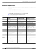
Hardware Installation Guide for Cisco UCS E-Series Servers Hardware Requirements Hardware Requirements E-Series Servers reside in the Cisco 2900 series or 3900 series ISR G2.
Hardware Installation Guide for Cisco UCS E-Series Servers Hardware Requirements Table 1 E-Series Server Hardware at a Glance (continued) 2921, 29512, 3925, 3925e, 3945, 3945e 2921, 29512, 3925, 3925e, 3945, 3945e 2900 ISR G2—1 E-Series Server 2900 ISR G2—1 E-Series Server 2900 ISR G2—1 E-Series Server 2951 ISR G2—2 E-Series Servers 3900 ISR G2—1 E-Series Server 3900 ISR G2—1 E-Series Server Router Platforms 2911, 2921, 2951, 3925, 3925e, 3945, 3945e Maximum Number of E-Series Servers Per ISR G2 3
Hardware Installation Guide for Cisco UCS E-Series Servers Hardware Requirements Figure 1 Front Panel of the Single-Wide E-Series Server 1 Gigabit Ethernet Port 2 Management Port 3 Power Switch 4 LEDs for HDD1 5 Keyboard, Video, Mouse (KVM) Port 6 Hard Disk Drive 1 USB Use the KVM connector that is shipped with the E-Series Server (See Figure 2) 7 LEDs for HDD2 8 9 Hard Disk Drive 2 10 Reset Switch Cisco UCS E-Series Server Modules Hardware Installation Guide 4 OL-26447-01
Hardware Installation Guide for Cisco UCS E-Series Servers Hardware Requirements Figure 2 shows the KVM Connector Figure 2 KVM Connector 1 USB Connector 3 DB9 Connector 2 DB15 Connector Cisco UCS E-Series Server Modules Hardware Installation Guide 5
Hardware Installation Guide for Cisco UCS E-Series Servers Hardware Requirements Figure 3 Single-Wide E-Series Server 1 DIMM Slots 2 HDD 3 SD0 (The SD card in the SD0 card slot contains the Integrated Management Controller software and should always be present.
Hardware Installation Guide for Cisco UCS E-Series Servers Hardware Requirements Figure 4 1 Front Panel of the Double-Wide E-Series Server 2 Power Switch Reset Switch. Note This reset all CMOS settings. 3 LEDs 4 VGA Port 5 Serial Port 6 Dual SD card slots and cover Note Do not remove the SD card in the SD0 card slot when the system is in operation. The SD card in the SD0 card slot contains the Integrated Management Controller software and should always be present.
Hardware Installation Guide for Cisco UCS E-Series Servers Hardware Requirements Figure 5 1 Double-Wide E-Series Server 2 DIMM slots (Optional) PCIe assembly Available for HDD2, FCoE port, or 4-Gigabit Ethernet ports. 3 Hard Disk Drives (HDD0 and HDD1) E-Series Servers LED States There are LEDs on the E-Series Servers. Table 4 and Table 6 list the LED states.
Hardware Installation Guide for Cisco UCS E-Series Servers Hardware Requirements Table 4 LED M2 3 HOT D0A LED States for the Double-Wide E-Series Servers (continued) Color Indicates Off No Memory installed in this socket Green Memory M2 is installed Amber Memory M2 is installed, but fault was detected Green Temperature is in range Amber A high temperature has been detected on the CPU, power supply, or other internal sensors Green Status of hard drive activity is as follows: • Steady—Hard
Hardware Installation Guide for Cisco UCS E-Series Servers Hardware Requirements Table 4 LED States for the Double-Wide E-Series Servers (continued) LED Color Indicates Power LED Green Status is as follows: Amber • Steady—Cisco Integrated Management Controller and CPU are both operating normally • Blinking—CPU is operating normally and Cisco Integrated Management Controller is booting up Status is as follows: • Steady—Cisco Integrated Management Controller is operating normally and the CPU is
Hardware Installation Guide for Cisco UCS E-Series Servers Recommended Practices for Cisco UCS E-Series Servers Table 5 LED States for the Single-Wide E-Series Servers (continued) LED Color Indicates SYS Green Solid—Operation is normal Note If DRAM is not detected the SYS LED will still show solid green. Blinking—System is booting before entering EFI shell.
Hardware Installation Guide for Cisco UCS E-Series Servers Recommended Practices for Cisco UCS E-Series Servers • Before working on the router, turn off the power and unplug the power cord. • Disconnect all power sources before doing the following: – Installing or removing a router chassis – Working near power supplies • Do not work alone if potentially hazardous conditions exist. • Always check that power is disconnected from a circuit.
Hardware Installation Guide for Cisco UCS E-Series Servers Recommended Practices for Cisco UCS E-Series Servers • Install the server away from heating, ventilation, and air-conditioning (HVAC) system and other large building air movers. • Install the rack away from areas that may be affected by external vibrations, such garage areas where there may be moving vehicles or factories with heavy machinary. • Do not install in a rack that will be placed in a moving vehicle.
Hardware Installation Guide for Cisco UCS E-Series Servers Recommended Practices for Cisco UCS E-Series Servers Warning No user-serviceable parts inside. Do not open. Statement 1073 Warning Ultimate disposal of this product should be handled according to all national laws and regulations. Statement 1040 Warning Read the installation instructions before connecting the system to the power source. Statement 1004 Warning Installation of the equipment must comply with local and national electrical codes.
Hardware Installation Guide for Cisco UCS E-Series Servers Installing E-Series Servers in Cisco ISR G2 Routers Warning Class 1 laser product. Statement 1008 Warning Invisible laser radiation may be emitted from the end of the unterminated fiber cable or connector. Do not view directly with optical instruments. Viewing the laser output with certain optical instruments (for example, eye loupes, magnifiers, and microscopes) within a distance of 100 mm may pose an eye hazard.
Hardware Installation Guide for Cisco UCS E-Series Servers Installing E-Series Servers in Cisco ISR G2 Routers – Installing Blank Faceplates on Cisco ISR G2 Routers, page 18 – Removing Blank Faceplates from Cisco ISR G2 Routers, page 18 • Preparing Cisco Router Slots for Server Module Installation, page 18 – Installing Slot Dividers, page 19 – Removing Slot Dividers, page 20 – Installing the E-Series Servers, page 20 • Note Installing the E-Series Servers, page 20 Cisco 2900 series do not support onli
Hardware Installation Guide for Cisco UCS E-Series Servers Installing E-Series Servers in Cisco ISR G2 Routers Cisco UCS E-Series Server Module Hardware Installation Tasks Step 1 Connect the wrist strap clip to an unpainted portion of the chassis frame to channel unwanted ESD voltages to ground. Step 2 Turn off power to the router. Note Alternatively, the Cisco 3900 series routers support OI R for similar server modules and network modules.
Hardware Installation Guide for Cisco UCS E-Series Servers Installing E-Series Servers in Cisco ISR G2 Routers Installing Blank Faceplates on Cisco ISR G2 Routers To install a blank faceplate, perform the following steps: Step 1 Install the blank faceplate. See Figure 6. • (For blank faceplates with mounting screws) Align the captive screws with the screw holes on the chassis.
Hardware Installation Guide for Cisco UCS E-Series Servers Installing E-Series Servers in Cisco ISR G2 Routers Installing Slot Dividers Slot dividers (see Figure 7) are used to customize service module slots for the different form factors (Single-wide and Double-wide).
Hardware Installation Guide for Cisco UCS E-Series Servers Installing E-Series Servers in Cisco ISR G2 Routers Figure 9 Step 5 Tightening the Slot Divider in a Service Module Slot Proceed with hardware configuration tasks. Removing Slot Dividers Slot dividers are removed to permit use of double-wide E-Series Servers in modular router slots.
Hardware Installation Guide for Cisco UCS E-Series Servers Installing E-Series Servers in Cisco ISR G2 Routers Note Step 2 Tip Figure 10 Alternatively, the Cisco 3900 series routers support OIR for similar server modules and network modules. (See the “Online Insertion and Removal on a Cisco ISR G2 Router” section on page 22.) Remove the blank faceplates installed over the slot you intend to use. (See the “Installing and Removing Blank Faceplates” section on page 17.
Hardware Installation Guide for Cisco UCS E-Series Servers Installing E-Series Servers in Cisco ISR G2 Routers Figure 11 1 Installing a Double-Wide E-Series Server in a Cisco ISR G2 Router Double-wideE-Series Server 2 Router chassis Step 5 Push the module into place until you feel the edge connector seat securely into the connector on the router backplane. The module faceplate should contact the chassis rear panel.
Hardware Installation Guide for Cisco UCS E-Series Servers Installing E-Series Servers in Cisco ISR G2 Routers DETAILED STEPS Step 1 Command or Action Purpose enable Enables privileged EXEC mode. Enter your password if prompted. Example: Router> enable Step 2 ucse slot shutdown Shuts down the E-Series Server gracefully. Note Example: Router# ucse 4 shutdown Step 3 slot oir-stop hw-module sm Before proceeding with the next command, verify that the E-Series Server has shutdown.
Hardware Installation Guide for Cisco UCS E-Series Servers Installing E-Series Servers in Cisco ISR G2 Routers • RAID 1 (disk mirroring): Data is written to two disks, where the data in both disk drives is identical This provides complete data redundancy if one disk fails. • RAID 5 (disk striping with distributed parity): Data and parity information is striped and distributed across all disks in the array with distributed parity information.
Hardware Installation Guide for Cisco UCS E-Series Servers Installing E-Series Servers in Cisco ISR G2 Routers Figure 12 1 Replacing a Hard Disk Drive on the Single-Wide E-Series Server Captive Screws 2 Hard Disk Drive Assembly Cisco UCS E-Series Server Modules Hardware Installation Guide 25
Hardware Installation Guide for Cisco UCS E-Series Servers Installing E-Series Servers in Cisco ISR G2 Routers Figure 13 Step 4 Replacing a Hard Disk Drive on the Double-Wide E-Series Server 1 Hard Disk Drives 2 Hard Disk Drive Assembly 3 Cover Faceplate 4 Captive Screws on Hard Disk Drive Assembly (Optional) If the slot is empty, use the screwdriver to loosen the screws on the bracket to remove the bracket that is attached to the slot. See Figure 14. Go to Step 7.
Hardware Installation Guide for Cisco UCS E-Series Servers Installing E-Series Servers in Cisco ISR G2 Routers Figure 14 1 Empty HDD2 Slot Bracket 2 Captive Screws on Hard Disk Drive Assembly Step 5 (Optional) If there is a hard disk drive, use the screwdriver to loosen the captive screws on the hard disk drive assembly. Step 6 (Optional) To remove the faulty hard disk, pull the handle of the hard disk drive assembly and slide out the hard disk drive.
Hardware Installation Guide for Cisco UCS E-Series Servers Installing E-Series Servers in Cisco ISR G2 Routers Installing and Replacing the PCIe Assembly on the Double-Wide E-Series Servers PCIe Assembly Figure 15 shows the PCIe Assembly, which consists of a PCIe card, a flex assembly which connects the PCIe slot to the motherboard, and a plastic bracket which slides over the end of the PCIe card.
Hardware Installation Guide for Cisco UCS E-Series Servers Installing E-Series Servers in Cisco ISR G2 Routers Figure 16 Replacing the PCIe Assembly 1 Captive Screws on the Face Plate 2 Flex Assembly Screw 3 Plastic Bracket screw 4 PCIe Assembly Step 4 Remove the screw holding the flex assembly in place Step 5 Remove the two screws connecting the plastic bracket to the motherboard. Step 6 Disconnect the flex assembly connector from the motherboard. Step 7 Remove the PCIe assembly.
Hardware Installation Guide for Cisco UCS E-Series Servers Installing E-Series Servers in Cisco ISR G2 Routers Step 4 Slide the plastic bracket over the end of the PCIe card. Step 5 Slide the PCIe assembly into the server module. Step 6 Connect the flex assembly onto the motherboard. Be careful not to place any stress on the connector contacts. Step 7 Replace the screw that secures the flex assembly in place and tighten.
Hardware Installation Guide for Cisco UCS E-Series Servers Installing E-Series Servers in Cisco ISR G2 Routers Removing a DRAM DIMM Follow these steps to remove a DRAM DIMM: Step 1 Connect the wrist strap clip to an unpainted portion of the chassis frame to channel unwanted ESD voltages to ground. Step 2 Turn off power to the router. Alternatively, the Cisco 3900 series routers support OIR.
Hardware Installation Guide for Cisco UCS E-Series Servers Installing E-Series Servers in Cisco ISR G2 Routers Installing a DRAM DIMM Follow these steps to install a DRAM DIMM: Note You should start installing the DIMM memory from the innermost slot to the outermost slot. Step 1 Connect the wrist strap clip to an unpainted portion of the chassis frame to channel unwanted ESD voltages to ground. Step 2 Turn off power to the router. Alternatively, the Cisco 3900 series routers support OIR.
Hardware Installation Guide for Cisco UCS E-Series Servers Installing E-Series Servers in Cisco ISR G2 Routers Figure 19 Step 8 Installing a DRAM DIMM Replace the E-Series Server. Removing the COA In the event that you need to RMA your module, make sure that you retain the original Certificate of Authenticity (COA) label. The COA is the label from Microsoft with the code that enables their windows software.
Hardware Installation Guide for Cisco UCS E-Series Servers Related Documentation Figure 20 1 COA Label Placement Plastic pull label tray Note The COA label from Microsoft is single layer and not foldable. Cisco Integrated Management Controller Cisco Integrated Management Controller (CIMC) is a separate management module built into the motherboard. CIMC is the management service for the E-Series Servers.
Hardware Installation Guide for Cisco UCS E-Series Servers Related Documentation • Cisco Network Modules, Server Modules, and Interface Cards Regulatory Compliance and Safety Information • GUI Configuration Guide for Cisco UCS E-Series Servers Integrated Management Controller, Release 1.0 • CLI Configuration Guide for Cisco UCS E-Series Servers Integrated Management Controller, Release 1.
Hardware Installation Guide for Cisco UCS E-Series Servers Related Documentation Cisco UCS E-Series Server Modules Hardware Installation Guide 36 OL-26447-01