
Troubleshooting guide

Send document comments to ucs-docfeedback@cisco.com
23
Cisco UCS B22 Blade Server Installation and Service Note
OL-27513 -01
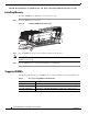
Removing a Blade Server Cover
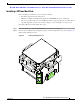
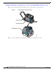
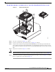
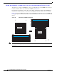
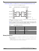
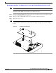
Figure 14 Replacing the Heat Sink
Step 5
Close the socket latch. See Figure 14, callout 1.
Step 6 Lock the socket latch into place with the hook. See Figure 14, callout 2.
Step 7 Using the tube of thermal compound (UCS-CPU-GREASE=) provided with replacement CPUs and
servers (Dow-Corning TC-1996, Intel D54816-0 or an equivalent may also be used), add a protective
film of thermal compound to the bottom of the heat sink (UCSB-HS-01-B22=) where it will contact the
CPU.
Step 8 Replace the heat sink. See Figure 14, callout 3.
Caution For proper cooling, align the arrows on the installed heat sink to point to the front and back of the blade.
Make sure that the heat sink fins are aligned to run along the length of the blade server (see Figure 14).
Step 9 Secure the heat sink to the motherboard by tightening the four captive screws. See Figure 14, callout 4.
Be sure to tighten in the order shown in Figure 14.
1
2
3
4
4
4
4
332669
B
C
A
D