
Troubleshooting guide

Send document comments to ucs-docfeedback@cisco.com
20
Cisco UCS B22 Blade Server Installation and Service Note
OL-27513 -01
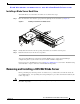
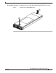
Removing a Blade Server Cover
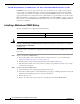
Removing a CPU and Heat Sink
To remove a CPU and heat sink, follow these steps:
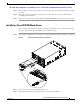
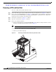
Step 1 Unscrew the four captive screws securing the heat sink to the motherboard. See Figure 11, callout 1.
Step 2 Remove the heat sink (N20-BHTS1=). See Figure 11, callout 2. Remove the old thermal compound from
the bottom of the heat sink using the cleaning kit (UCSX-HSCK= ) available from Cisco. Follow the
instructions on the two bottles of cleaning solvent.
Step 3 Unhook the socket latch. See Figure 11, callout 3.
Step 4 Open the socket latch. See Figure 11, callout 4.
Step 5 Remove the old CPU as follows:
a. Place the CPU alignment tool (UCS-CPU-EN-PNP=) on the CPU bezel aligned with the A1 arrow
pointing to the CPU registration mark as shown in Figure 13.
Note The CPU alignment tool is included with each CPU option kit.
b. Press the side lever on the tool to grasp the installed CPU.
c. Lift the tool and CPU straight up.
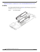
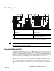
Figure 11 Removing The Heat Sink and Accessing the CPU Socket
3
1
2
1
1
1
4
332667