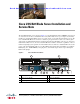
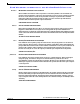
Se n d d o c u m e n t c o m m e n t s t o u c s - d o c f e e d b a ck @ c i s c o . c o m Cisco UCS B22 Blade Server Installation and Service Note The UCS B22 M3 blade server (shown in Figure 1) is a half-width blade with 12 DIMM slots;it supports one dedicated slot for Cisco's Virtual Interface Card (VIC) 1240, and one open adapter slot. You may install up to eight UCS B22 Blade Servers to a UCS chassis, or mix with other UCS blade servers.
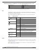
Se n d d o c u m e n t c o m m e n t s t o u c s - d o c f e e d b a ck @ c i s c o . c o m 4 Hard drive bay 1 10 Reset button access 5 Hard drive bay 2 11 Beaconing LED and button 6 Power button and LED 1. Each server has a blank plastic asset tag that pulls out of the front panel, provided so you can add your own asset tracking label without interfering with the intended air flow.
Se n d d o c u m e n t c o m m e n t s t o u c s - d o c f e e d b a ck @ c i s c o . c o m The power button and LED allows you to manually take a server temporarily out of service but leave it in a state where it can be restarted quickly.
Se n d d o c u m e n t c o m m e n t s t o u c s - d o c f e e d b a ck @ c i s c o . c o m Warning IMPORTANT SAFETY INSTRUCTIONS This warning symbol means danger. You are in a situation that could cause bodily injury. Before you work on any equipment, be aware of the hazards involved with electrical circuitry and be familiar with standard practices for preventing accidents.
Se n d d o c u m e n t c o m m e n t s t o u c s - d o c f e e d b a ck @ c i s c o . c o m Avvertenza IMPORTANTI ISTRUZIONI SULLA SICUREZZA Questo simbolo di avvertenza indica un pericolo. La situazione potrebbe causare infortuni alle persone. Prima di intervenire su qualsiasi apparecchiatura, occorre essere al corrente dei pericoli relativi ai circuiti elettrici e conoscere le procedure standard per la prevenzione di incidenti.
Se n d d o c u m e n t c o m m e n t s t o u c s - d o c f e e d b a ck @ c i s c o .
Se n d d o c u m e n t c o m m e n t s t o u c s - d o c f e e d b a ck @ c i s c o . c o m Aviso INSTRUÇÕES IMPORTANTES DE SEGURANÇA Este símbolo de aviso significa perigo. Você se encontra em uma situação em que há risco de lesões corporais. Antes de trabalhar com qualquer equipamento, esteja ciente dos riscos que envolvem os circuitos elétricos e familiarize-se com as práticas padrão de prevenção de acidentes.
Se n d d o c u m e n t c o m m e n t s t o u c s - d o c f e e d b a ck @ c i s c o .
Installing and Removing a Blade Server Hard Drive Se n d d o c u m e n t c o m m e n t s t o u c s - d o c f e e d b a ck @ c i s c o . c o m Installing and Removing a Blade Server Hard Drive There are up to 2 front-accessible, hot-swappable, 2.5-inch drives per blade. An LSI 2002 RAID controller is embedded in the motherboard (a Cisco exclusive and not separately replaceable) and it supports RAID 0 and 1. You can remove blade server hard drives without removing the blade server from the chassis.
Installing and Removing a Blade Server Hard Drive Se n d d o c u m e n t c o m m e n t s t o u c s - d o c f e e d b a ck @ c i s c o . c o m Table 2 shows the drives supported in this blade server.
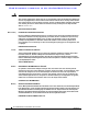
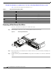
Removing and Installing a UCS B22 Blade Server Se n d d o c u m e n t c o m m e n t s t o u c s - d o c f e e d b a ck @ c i s c o . c o m Installing a Blade Server Hard Drive To install a blade server hard drive in a blade server, follow these steps: Step 1 Place the hard drive lever into the open position by pushing the release button (see Figure 4).
Removing and Installing a UCS B22 Blade Server Se n d d o c u m e n t c o m m e n t s t o u c s - d o c f e e d b a ck @ c i s c o . c o m Shutting Down and Powering Off A Blade Server The server can run in two power modes: • Main power mode—Power is supplied to all server components and any operating system on your hard drives can run. • Standby power mode—Power is supplied only to the service processor and the cooling fans and it is safe to power off the server from this mode.
Removing and Installing a UCS B22 Blade Server Se n d d o c u m e n t c o m m e n t s t o u c s - d o c f e e d b a ck @ c i s c o . c o m Step 3 Slide the blade part of the way out of the chassis, and place your other hand under the blade to support its weight. Step 4 Once removed, place the blade on an antistatic mat or antistatic foam if you are not immediately reinstalling it into another slot.
Secure Digital (SD) Card Access Se n d d o c u m e n t c o m m e n t s t o u c s - d o c f e e d b a ck @ c i s c o . c o m Step 4 Press the ejector lever so that it catches the edge of the chassis and presses the blade server all the way in. Step 5 Tighten the captive screw on the front of the blade to no more than 3 in-lbs. Tightening with bare fingers only is unlikely to lead to stripped or damaged captive screws. Step 6 Power on the server.
Removing a Blade Server Cover Se n d d o c u m e n t c o m m e n t s t o u c s - d o c f e e d b a ck @ c i s c o .
Removing a Blade Server Cover Se n d d o c u m e n t c o m m e n t s t o u c s - d o c f e e d b a ck @ c i s c o . c o m Air Baffles The air baffles (UCSB-BAFF-B22-M3=) shown in Figure 8 ship with this server, as they direct and improve air flow for the server components. No tools are necessary to install them, just place them over the DIMMs as shown, aligned to the standoffs.
Removing a Blade Server Cover Se n d d o c u m e n t c o m m e n t s t o u c s - d o c f e e d b a ck @ c i s c o . c o m Internal Components Figure 9 calls out the various components within the blade server.
Removing a Blade Server Cover Se n d d o c u m e n t c o m m e n t s t o u c s - d o c f e e d b a ck @ c i s c o . c o m If DIMM insertion errors are detected, they may cause the blade discovery to fail and errors will be reported in the server POST information, viewable using the UCS Manager GUI or CLI. UCS blade servers require specific rules to be followed when populating DIMMs in a blade server, and the rules depend on the blade server model.
Removing a Blade Server Cover Se n d d o c u m e n t c o m m e n t s t o u c s - d o c f e e d b a ck @ c i s c o . c o m Figure 10 Removing and Replacing a Motherboard CMOS Battery + 333339 CPU 1 CPU Replacement You can order your blade server with two CPUs, or upgrade later to a second CPU. Both CPUs must be of the same type, and memory in slots intended for the second CPU will not be recognized if the second CPU is not present (see Memory Arrangement).
Removing a Blade Server Cover Se n d d o c u m e n t c o m m e n t s t o u c s - d o c f e e d b a ck @ c i s c o . c o m Removing a CPU and Heat Sink To remove a CPU and heat sink, follow these steps: Step 1 Unscrew the four captive screws securing the heat sink to the motherboard. See Figure 11, callout 1. Step 2 Remove the heat sink (N20-BHTS1=). See Figure 11, callout 2. Remove the old thermal compound from the bottom of the heat sink using the cleaning kit (UCSX-HSCK= ) available from Cisco.
Removing a Blade Server Cover Se n d d o c u m e n t c o m m e n t s t o u c s - d o c f e e d b a ck @ c i s c o . c o m Installing a CPU and Heat Sink Before installing a new CPU in a server, verify the following: • The CPU is supported for that model server. • A BIOS is available and installed that supports the CPU/DIMM and server combination. • The service profile for this server in UCS Manager will recognize and allow the new CPU.
Removing a Blade Server Cover Se n d d o c u m e n t c o m m e n t s t o u c s - d o c f e e d b a ck @ c i s c o . c o m Step 3 Place the alignment tool with a CPU loaded on the base aligned as shown in Figure 13. Figure 13 Proper Alignment and CPU Insertion Side lever Central button 332668 Alignment mark Step 4 Press the central button on the alignment tool to release the CPU into the socket.
Removing a Blade Server Cover Se n d d o c u m e n t c o m m e n t s t o u c s - d o c f e e d b a ck @ c i s c o . c o m Figure 14 Replacing the Heat Sink 4 3 C 4 B A 4 D 4 1 332669 2 Step 5 Close the socket latch. See Figure 14, callout 1. Step 6 Lock the socket latch into place with the hook. See Figure 14, callout 2.
Removing a Blade Server Cover Se n d d o c u m e n t c o m m e n t s t o u c s - d o c f e e d b a ck @ c i s c o . c o m Installing Memory To install a DIMM into the B22 blade server, follow these steps: Step 1 Open both DIMM connector latches. Figure 15 Installing DIMMs in the Blade Server 1 2 3 332666 2 1 3 Step 2 Note Step 3 Press the DIMM into its slot evenly on both ends until it clicks into place. Be sure that the notch in the DIMM aligns with the slot.
Removing a Blade Server Cover Se n d d o c u m e n t c o m m e n t s t o u c s - d o c f e e d b a ck @ c i s c o . c o m Low-Voltage DIMM Considerations The server can be ordered with low-voltage (1.35 V) DIMMs or mixed-voltage (1.35V/1.5 V) DIMMs. There is a setting in the BIOS Setup utility that you can use to change the DDR memory mode when the server has all low-voltage DIMMs installed.
Removing a Blade Server Cover Se n d d o c u m e n t c o m m e n t s t o u c s - d o c f e e d b a ck @ c i s c o . c o m The blade server contains 12 DIMM slots—six for each CPU. Each set of six DIMM slots is arranged into three channels, where each channel has 2 DIMMs (see Figure 16). Each channel is identified by a letter—B, C, D for CPU1, and F, G, H for CPU 2. Each DIMM slot is identified by a number, either 0 or 1. Note that each DIMM slot 0 is blue, while each slot 1 is black.
Removing a Blade Server Cover Se n d d o c u m e n t c o m m e n t s t o u c s - d o c f e e d b a ck @ c i s c o .
Removing a Blade Server Cover Se n d d o c u m e n t c o m m e n t s t o u c s - d o c f e e d b a ck @ c i s c o . c o m Bandwidth and Performance Recommendations for achieving performance of 1600 MHz on B22 M3 servers: • Ensure that both the installed CPU and the selected DIMMs support operation at 1600 MHz. If either cannot support this, the pair will run at the highest speeed of the slower of the two. • Ensure the server is running the 2.0(2) or later BIOS version.
Removing a Blade Server Cover Se n d d o c u m e n t c o m m e n t s t o u c s - d o c f e e d b a ck @ c i s c o . c o m Note You must remove the adapter card to service the modular LOM. To install a modular LOM card on the blade server, follow these steps: Step 1 Position the modular LOM’s board connector above the motherboard connector and align the captive screw to the standoff post on the motherboard. Step 2 Firmly press the modular LOM’s board connector into the motherboard connector.
Removing a Blade Server Cover Se n d d o c u m e n t c o m m e n t s t o u c s - d o c f e e d b a ck @ c i s c o . c o m Installing an Adapter Card The network adapters and interface cards all have a shared installation process. The following options are available: Table 7 Note Adapter Card Options Cisco Product ID Name UCS-VIC-M82-8P VIC 1280 - Dual 40Gb capable Virtual Interface Card Use of this server may require an upgrade to the IOM in the chassis.
Trusted Platform Module Se n d d o c u m e n t c o m m e n t s t o u c s - d o c f e e d b a ck @ c i s c o . c o m Figure 19 Installing an Adapter Card 3 2 1 331730 1 Trusted Platform Module The Trusted Platform Module (TPM, Cisco Product ID UCSX-TPM1-001) is a component that can securely store artifacts used to authenticate the server. These artifacts can include passwords, certificates, or encryption keys.
Server Troubleshooting Se n d d o c u m e n t c o m m e n t s t o u c s - d o c f e e d b a ck @ c i s c o . c o m Step 4 On the Advanced tab, select Trusted Computing and press Enter. Step 5 Set the TPM Support optionto Enable. Step 6 Press F10 to save and exit. Allow the server to finish booting. Server Troubleshooting For general server troubleshooting information, refer to the "Troubleshooting Server Hardware" chapter of the Cisco UCS Troubleshooting Guide.
Related Documentation Se n d d o c u m e n t c o m m e n t s t o u c s - d o c f e e d b a ck @ c i s c o . c o m Subscribe to the What’s New in Cisco Product Documentation as an RSS feed and set content to be delivered directly to your desktop using a reader application. The RSS feeds are a free service. Cisco currently supports RSS Version 2.0. Cisco and the Cisco logo are trademarks or registered trademarks of Cisco and/or its affiliates in the U.S. and other countries.
Related Documentation Se n d d o c u m e n t c o m m e n t s t o u c s - d o c f e e d b a ck @ c i s c o .