Quick Start Guide Cisco uBR10012 Universal Broadband Router Hardware Installation Guide INCLUDING LICENSE AND WARRANTY 1 Cisco One-Year Limited Hardware Warranty Terms 2 Overview 3 Site Preparation 4 Chassis Installation 5 Connecting Cables 6 Power On the Cisco uBR10012 Router 7 Configuring the Cisco uBR10012 Router at Startup 8 Troubleshooting 9 Related Documentation 10 Obtaining Documentation 11 Documentation Feedback 12 Cisco Product Security Overview 13 Obtaining Technical Assistance
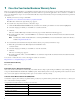
1 Cisco One-Year Limited Hardware Warranty Terms There are special terms applicable to your hardware warranty and various services that you can use during the warranty period. Your formal Warranty Statement, including the warranties and license agreements applicable to Cisco software, is available on Cisco.com. Follow these steps to access and download the Cisco Information Packet and your warranty and license agreements from Cisco.com. 1. Launch your browser, and go to this URL: http://www.cisco.
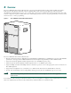
2 Overview The Cisco uBR10012 universal broadband router is an aggregation platform that provides a high-end, high-performance, high-capacity Cable Modem Termination System (CMTS) solution. The system provides high-speed data, broadband entertainment, and IP telephony services over a coaxial cable connection to residential and commercial subscribers using cable modems or digital set-top boxes (STBs).
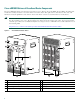
Cisco uBR10012 Universal Broadband Router Components The Cisco uBR10012 chassis is designed for front and rear access. The two AC or DC PEMs, the two PRE1s, the LCD panel, and the fan assembly module are accessed from the front of the chassis. The eight slots for cable interface line cards, four full-slots for network uplink line cards, and two slots for the TCC+ cards are accessed from the rear of the chassis.
3 Site Preparation Do not unpack the system until you are ready to install it. Keep the chassis in the shipping container to prevent accidental damage until you determine an installation site. Before you install the Cisco uBR10012 universal broadband router, review the following: • The environmental conditions your installation site must meet to maintain normal operation. • The power requirements that must be in place at your installation sites. • The cabling requirements for your installation sites.
Power Guidelines Follow these precautions and recommendations when planning power connections to the Cisco uBR10012 router: • Check the power at your site before installation and periodically after installation to ensure that you are receiving clean power. Install a power conditioner if necessary. • Provide proper grounding. • Make sure that frame ground is tied to a single building ground.
Fiber-Optic Connections The specifications for single-mode, fiber-optic transmissions are outlined in Table 3. Table 3 Fiber-Optic Transmission Characteristics Characteristic Permissible Value Characteristic Permissible Value Transmitter output power –15 to –8 dBm Wavelength 1261 to 1360 nm Receiver sensitivity –28 to –8 dBm Maximum span 9 miles (14.5 km) Note Do not exceed the specified distance limits.
Verifying Contents After Unpacking Power cables, manuals, and other additional items are packaged in separate boxes. After you have unpacked the system, verify that you have received all the required components and documentation. Step 1 Using the packing list as a guide, verify that you have received everything that is listed, including the following: a. System hardware documentation and software documentation (if ordered) b.
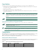
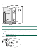
Figure 3 Removing the Front Cover POWER MISWIR E FAULT CISCO 10000 CO NS O CO LE IPSU SA TUS POW POWE ER R MISWIR E FAU ULT LLT IPSUM SANCT IPSUM CISCO 10000 NS O AU LE X POWER MISWIR E FAULT AU POW PO WE ER R MISWIR E FAU ULT LLT X AC TI VI ET AC TY TI HE NK VI ET ET TY HE LI SL NK RN ET 1 OT 0 OT SL 1 OT SL 0 OT SL RN LI ALARMS ALARMS AC O AC C O R M IT AJ IN IC O O FA U S IL R M M IT AJ IN IC O O ST AT FA U S 95486 IL AL R R PERFORMAN
Set the fan assembly module aside. Step 3 You do not need to remove the fan assembly cable. The fan assembly pulls away from the cable as the module is removed from the router. Note Remove the PEMs (DC and AC) DC PEM To remove the DC PEMs from the Cisco uBR10012 router, follow this procedure: Step 1 Verify that the first DC PEM you are removing is turned off by pushing the three-levered power switch down to the OFF (0) position. Tape the switch in the OFF position.
AC PEM Because of safety compliance issues with the power cords, the AC PEM power rating is 200–240 VAC at 13 A instead of 16 A. Caution To remove AC PEMs from the Cisco uBR10012 router, follow this procedure: Step 1 Verify that the power switch on the AC PEM is turned off. See Figure 6. Step 2 Unplug and remove the AC-input power cord from the chassis cord clips, if applicable. Tape the AC power switch in the OFF position. Step 3 Use a screwdriver to loosen the captive screws (top and bottom).
Remove the PREs Step 1 Unscrew the captive screws (top and bottom) on the PRE module. See Figure 7. Step 2 Simultaneously pivot both ejector levers away from each other to disengage the PRE module from the backplane. Step 3 Slide the PRE module out of the slot and place it on an antistatic surface.
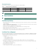
Figure 8 Removing Line Cards US0 US2 US1 US0 US3 US2 US1 US0 US4 US3 US2 US1 US0 US4 US4 US3 US2 US1 US4 US3 US2 US4 US3 US5 US7 US6 US0 US6 US8 US7 US6 US9 US8 US7 US9 US8 IL FA IL IL US6 US1 US2 US3 US0 US1 US0 US2 US1 US0 US3 US2 US1 US0 US3 US2 US1 US0 US4 US7 US8 US4 US3 US2 US1 US4 US3 US2 US4 US3 US6 US5 US7 US6 US8 US7 US6 US5 US8 US7 US6 US5 US9 US7 US6 US5 US9 US8 US8 US7 US6 US5 US9 US9 US8 US7 US6 US9
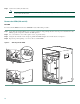
Figure 9 shows how to attach the brackets to flush-mount the chassis with the rear forward. Figure 10 shows how to attach the brackets to flush-mount the chassis with the front forward and how to attach the brackets to offset-mount the chassis with the front forward. You must use three screws to install each large bracket and two screws to install each small bracket.
Installing the Chassis in the Rack With the fan assembly, PEMs, PREs, line cards, and uplink cards removed from the chassis, and the mounting brackets installed, the Cisco uBR10012 chassis is ready for installation in a 19-inch equipment rack or Telco rack. Caution The Cisco uBR10012 chassis with all the components removed still weighs 60 lbs (27.22 kg). Take all necessary precautions when rack-mounting this chassis.
Note The chassis is usually installed in the bottom of the rack. Step 5 Maneuver the chassis into position in the rack. Step 6 Align the mounting bracket holes with the rack post holes and attach the chassis to the rack with the appropriate-sized screws (performed by the third person, unless the chassis is resting on the bottom of the rack or a shelf). Note Figure 11 Figure 11 shows the chassis flush-mounted at the rear. The procedure is identical for the other mounting methods.
Recommended Tools and Supplies Qty Description Comments 1 Number 2 Phillips screwdriver — 1 Wire stripping tool — 1 Crimping tool Must fit diameter of grounding lugs. 1 2-hole grounding lug Included in accessory kit shipped with the Cisco uBR10012 router. 1 Grounding wire 6 AWG (16 mm2), customer provided. 2 M5 PEM screws with captive, locking washers Included in accessory kit shipped with the Cisco uBR10012 router.
Connecting –48/–60 VDC Power to the Cisco uBR10012 Router The DC power sources can be present at the site, or they can be provided by the optional 2400W AC-input power shelf. If you are using the 2400W AC-input power shelf, be certain you have already installed it, as described in the 2400W AC-Input Power Shelf Installation Guide. Note For full power redundancy, each terminal block must be connected to a separate power source.
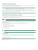
Step 6 If you are connecting visual or audio alarm indicators to your system, go to the “Connecting the Alarm Indicators” section on page 19. Step 7 If you are not connecting any alarm indicators, go to the “Replacing the Modules” section on page 20. Connecting the Alarm Indicators The Cisco uBR10012 router provides relay contacts for optional (customer-supplied) audible or visual alarm indicators. Relay contacts are provided for three levels of severity.
Figure 14 Alarm Terminal Block Connections MINOR MINOR MAJOR NC COM NO NC COM NO CRITICAL NC COM NO NC COM NO 98749 ALARMS 60 VDC 1A MAX Replacing the Modules PRE Modules Step 1 Align the PRE module with the card guides in the slot. See Figure 15. Step 2 Slide the card into the slot until you can feel it seat in the backplane connectors. Step 3 Close the ejector levers to secure the card in the backplane, and tighten the captive screws to secure the card in the chassis.
DC Power Entry Modules Step 1 Verify that the power switch is in the OFF position. Step 2 Position the first DC PEM in the power bay and push it forward, verifying that it goes all the way in and makes a secure connection with the backplane. See Figure 16. Step 3 Tighten the captive screws to secure the DC PEM. Step 4 Repeat these steps to install the second DC PEM. Caution Make sure that the alarm cables and the DC cables are out of the way before you slide the PEMs into the power bay.
For fully redundant operation, each AC PEM should use separate power sources. Alternately, you can use an uninterruptable power supply (UPS).
Line Cards and Uplink Cards The Cisco uBR10-LCP2-MC16 or -MC28 cable interface line card must be installed as one unit. Do not install the card adapter carrier (Cisco uBR10-LCP2) without the line card. Cisco uBR-MC5x20 cards are used in the example. Always check the captive screws that secure the line card to the adapter card (card carrier) before installation. Caution Step 1 Align the upper and lower edges of the card with the upper and lower guides in the chassis. See Figure 19.
Step 1 Grasp the faceplate of the line card with one hand and place your other hand under the card carrier (to support the weight of the card). Position the card in front of the slot splitter. Step 2 Carefully align the upper and lower edges of the line card with the upper and lower guides in the slot splitter, and slide the line card about half-way into the splitter.
Figure 20 Console and Auxiliary Port Connection on the PRE Module Pin 1 Pin 2 Pin 3 Pin 6 CISCO 10000 CISCO 10000 C C O O N N S S O O LE LE AU AU X X LIN LIN K K E E TH TH E E 1 OT 0 T OT E SL N K SL 1 OT 0 OT SL SL R LIN R N LIN K E T Crossover cable to DB9 or DB25 connector Console port Auxiliary port 98751 How to identify a crossover cable Auxiliary Port The auxiliary port provides a connection for a modem to allow remote access to the router and its
The color of the wire connected to pin 1 (left-most) on the connector at one end of the cable, should be the same color as the wire connected to the left-most pin on the connector at the other end of the cable. The same rule applies to pins 2 through pin 8 on each connector.
Connecting the Data Network Cables Attenuation The Cisco MC16C. Cisco MC16S, and MC28C line cards with the adapter card may require an attenuator in the downstream configuration. The output is higher (+42 dBmV) and may overload the external upconverter input. Overdriving an external upconverter may cause degraded bit error rate (BER), clipping and compression or distortion in the upconverter and possible interference with adjacent channels.
Warning Class 1 laser product. Statement 1008. Warning Invisible laser radiation present. Statement 1016. Warning Invisible laser radiation may be emitted from disconnected fibers or connectors. Do not stare into beams or view directly with optical instruments. Statement 1051. Equipment • Fiber-optic cables To connect the fiber cable to the uplink line card, follow this procedure: Step 1 Remove the protective cap from the fiber-optic cable connectors.
• The console terminal or modem is cabled and turned on. • A PCMCIA flash memory card is installed in the PRE module. You are now ready to power on the system for the first time using the following procedure. DC PEM Step 1 Verify that each DC PEM is turned OFF (0). See Figure 23. Step 2 Remove the tape from the circuit breaker switch handle. Step 3 Turn on power at the power supply that is suppling the DC power for the chassis.
d. If either the Single Fan Failure LED or the Multiple Fan Failure LED comes on (yellow), see the “Troubleshooting” section on page 35. e. The Fail LED on each PRE module comes on (yellow) briefly during the power-on sequence, but then should turn off. If the Fail LED does not go off on either PRE, verify that the ejector levers are fully closed and that the captive screws have been tightened. If necessary, remove the PRE from the chassis and reinsert it or replace it.
ROM: System Bootstrap, Version 12.0(9r)SL1, RELEASE SOFTWARE (fc1) BOOTFLASH: 10012 Software (C10K-EBOOT-M), Released Version 12.1(5) System returned to ROM by reload at 12:59:35 PDT Thu Apr 19 2001 System restarted at 13:00:51 PDT Thu Apr 19 2001 cisco C10012 (PRE-RP) processor with 98304K/32768K bytes of memory. Processor board ID ABCDEFEDCBA R7000 CPU at 262Mhz, Implementation 39, Rev 2.1, 256KB L2, 2048KB L3 Cache Backplane version 1.
Configuring the System Using System Configuration Dialog To perform a basic configuration using the System Configuration Dialog, follow this procedure: Step 1 The dialog starts by asking if you want to continue with the configuration dialog. Enter Yes. To return to the enable prompt, enter No. --- System Configuration Dialog --Continue with configuration dialog? [yes/no]: yes Step 2 Enter Yes to perform a basic management setup. Enter No to perform an extended configuration setup.
Step 1 To achieve network connectivity, enter the interface for the Fast Ethernet interface. Enter interface name used to connect to the management network from the above interface summary: FastEthernet0/0/0 Step 2 Accept the default value for the type of connector. RJ-45 is the only connector that can be used on the Cisco uBR10012 router Ethernet port.
Basic Configuration in Global Configuration Mode The following command sequence allows you to perform a configuration similar to that generated by the setup command: Router> configure terminal Router(config)# hostname c10012 Router(config)# enable secret Router(config)# enable password Router(config)# snmp-server community public Router(config)# ip routing Router(config)# interface FastEthernet0/0/0 Router(config-if)# no shutdown Router(config-if)# media-type 100BaseX Router(config-if)#
8 Troubleshooting The following section provides troubleshooting tips and procedures that you can use to verify your system setup. Before You Call for Technical Assistance If you are unable to solve the problem easily, contact a Cisco customer service representative for assistance and further instructions. See the “Obtaining Technical Assistance” section on page 41.
Solving Startup Problems by Using a Subsystems Approach Because a startup problem is usually caused by a single component, it is more efficient to isolate the problem to a subsystem rather than troubleshoot each component in the system.
Table 5 Troubleshooting Tips (continued) Symptom Action DC PEM FAULT LED or MISWIRE LED If the FAULT LED is on, check the power source, and verify that the PEM is is on. properly installed. If the MISWIRE LED is on, the –48/–60 VDC and return (RTN+) wires are reversed. Power off the PEM, remove it from the chassis, and reconnect the wires correctly. AC PEM POWER or FAULT LED is on. If the POWER LED on the AC PEM is off, check the AC power source.
Table 5 Troubleshooting Tips (continued) Symptom Action ENABLED LED on the line cards or on the uplink cards does not go on. 1. If the ENABLED LED is off, first verify that the card has been enabled and ENABLED LED remains off when a card has not been configured and enabled. 2. If a port has been enabled but its corresponding ENABLED LED is still off, reseat the card in its slot (you do not have to turn off the system power when removing or replacing the card).
9 Related Documentation Chassis Installation Documentation Cisco uBR10012 Universal Broadband Hardware Installation Guide at the following URL: http://www.cisco.com/univercd/cc/td/doc/product/cable/ubr10k/ubr10012/hig/index.htm FRU Documentation For documentation about the different modules used with the Cisco uBR10012 router, go to the following URL: http://www.cisco.com/univercd/cc/td/doc/product/cable/ubr10k/ubr10012/frus/index.
Product Documentation DVD Cisco documentation and additional literature are available in the Product Documentation DVD package, which may have shipped with your product. The Product Documentation DVD is updated regularly and may be more current than printed documentation. The Product Documentation DVD is a comprehensive library of technical product documentation on portable media.
From this site, you can perform these tasks: • Report security vulnerabilities in Cisco products. • Obtain assistance with security incidents that involve Cisco products. • Register to receive security information from Cisco. A current list of security advisories and notices for Cisco products is available at this URL: http://www.cisco.
Note Use the Cisco Product Identification (CPI) tool to locate your product serial number before submitting a web or phone request for service. You can access the CPI tool from the Cisco Technical Support & Documentation website by clicking the Tools & Resources link under Documentation & Tools. Choose Cisco Product Identification Tool from the Alphabetical Index drop-down list, or click the Cisco Product Identification Tool link under Alerts & RMAs.
• Packet magazine is the Cisco Systems technical user magazine for maximizing Internet and networking investments. Each quarter, Packet delivers coverage of the latest industry trends, technology breakthroughs, and Cisco products and solutions, as well as network deployment and troubleshooting tips, configuration examples, customer case studies, certification and training information, and links to scores of in-depth online resources. You can access Packet magazine at this URL: http://www.cisco.
Corporate Headquarters Cisco Systems, Inc. 170 West Tasman Drive San Jose, CA 95134-1706 USA www.cisco.com Tel: 408 526-4000 800 553-NETS (6387) Fax: 408 526-4100 European Headquarters Cisco Systems International BV Haarlerbergpark Haarlerbergweg 13-19 1101 CH Amsterdam The Netherlands www-europe.cisco.com Tel: 31 0 20 357 1000 Fax: 31 0 20 357 1100 Americas Headquarters Cisco Systems, Inc. 170 West Tasman Drive San Jose, CA 95134-1706 USA www.cisco.