
Specifications


78
OL-4923-01 B0
Console and Auxiliary Y-Cable Pinouts
The console and auxiliary Y-cables allow you to simultaneously connect the console ports or auxiliary
ports on two RSPs (configured as system active and slave in RSP slots 2 and 3 in the Cisco 7507, and
RSP slots 6 and 7 in the Cisco 7513 to one console terminal or external auxiliary device (such as a
modem).
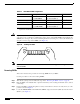
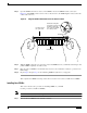
The two Y- cables (Product Numbers CAB-RSP2CON=, shown in Figure 6 and CAB-RSP2AUX=,
shown in Figure 7) ship with the router and are available as spare parts. The console Y-cable pinouts are
listed in Table 16, and the auxiliary Y-cable pinouts are listed in Table 17.
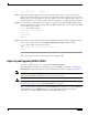
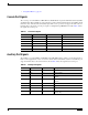
Table 16 Console Y-Cable Signals (CAB-RSP2CON=)
Female DB-25 Pins Male3 DB-25 Pins Signal Description
P1-1 J1-1 and J2-1 Ground
P1-2 J1-2, and J2-2 Receive Data (RxD)
P1-3 J1-3 and J2-3 Transmit Data (TxD)
P1-4 J1-4 and J2-4 Clear To Send (CTS); looped to 5
P1-5 J1-5 and J2-5 Request To Send (RTS); looped to 4
P1-6 J1-6 and J2-6 Data Set Ready (DSR)
P1-7 J1-7 and J2-7 Ground
P1-8 J1-8 and J2-8 Data Carrier Detect (DCD)
P1-13 J1-13 and J2-13 YCBL Detect Ground
P1-19 J1-19 and J2-19 YCBL Detect
P1-20 J1-20 and J2-20 Data Terminal Ready (DTR)
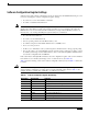
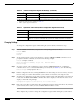
Table 17 Auxiliary Y-Cable Signals (CAB-RSP2AUX=)
Male DB-25 Pins Female3 DB-25 Pins Signal Description
P1-1 J1-1 and J2-1 Ground
P1-2 J1-2 and J2-2 TxD
P1-3 J1-3 and J2-3 RxD
P1-4 J1-4 and J2-4 RTS
P1-5 J1-5 and J2-5 CTS
P1-7 J1-7 and J2-7 Ground
P1-8 J1-8 and J2-8 DCD
P1-13 J1-13 and J2-13 YCBL Detect
P1-19 J1-19 and J2-19 YCBL Detect Ground
P1-20 J1--20 and J2-20 DTR
P1-22 J1-22 and J2-22 Ring