
Specifications


62
OL-4923-01 B0
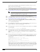
Figure 12 RSP2 LEDs, Active/Standby Switch, and Reset Switch (Vertical Partial Front-Panel View)
Caution The reset switch (see Figure 12) resets the RSP2 and the entire system. To prevent system errors and
problems, use it only at the direction of your Cisco-certified service representative.
Verifying System Startup Sequence
By checking the state of the LEDs, you can determine when and where the system failed in the startup
sequence. Because you turn on the system power with the on/off switches on each power supply, it is
easiest to observe the startup behavior from the rear of the router. Use the following descriptions of the
normal startup sequence to isolate the problem, and then use the troubleshooting procedures wherever
the system fails to operate as expected. If you are able to isolate the problem to a faulty hardware
component, or if you are unable to successfully restart the system, see the “Obtaining Technical
Assistance” section on page 86 for instructions on contacting a service representative.
Note The time required for the system to initialize (boot) might vary with different router configurations and
the amount of memory that must be initialized. During the system startup sequence, the time required to
initialize the memory (not necessarily the entire boot sequence) in a system that contains 128 MB of
DRAM might be longer than in a system that contains less DRAM.
NORMAL
CPU HALT
H7187
RESET
SLOT 1
SLOT 0
MASTER
SLAVE
STANDBY/ACTIVE
Standby Active