
Specifications

6
OL-4923-01 B0
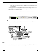
Caution Before you replace an RSP2 in a system with one RSP2, back up the running configuration to a TFTP
file server or to Flash memory so you can retrieve it later. If the configuration is not saved, the entire
configuration will be lost—inside the NVRAM on the removed RSP2—and you will have to reenter the
entire configuration manually. For instructions on how to save the configuration file, see the “Saving and
Retrieving the Configuration File” section on page 66. This procedure is not necessary if you are
temporarily removing an RSP2; lithium batteries retain the configuration in memory until you replace
the RSP2 in the system.
Flash Memory
The Flash memory card for the RSP2 is an 16- or 20- Flash memory card, which conforms with the PC
Card normally Personal Computer Memory Card International Association (PCMCIA) format.
Both the onboard 8-MB and the 16- or 20-MB Flash memory card (PCMCIA cards) allow you to
remotely load and store multiple Cisco IOS software and microcode images. You can download a new
image over the network or from a local server and then add the new image to Flash memory or replace
the existing files. You can then boot routers either manually or automatically from any of the stored
images. Flash memory also functions as a TFTP server to allow other servers to boot remotely from
stored images or to copy them into their own Flash memory.
Caution To prevent system problems, use Flash memory cards in the RSP2 that were formatted on an RP, RSP1,
or RSP7000 running Cisco IOS Release 11.1(8)CA1 or a later release of 11.1 CA1. You cannot use Flash
memory cards on the RSP2 (as storage or boot devices) that were formatted on an RP, RSP1, or RSP7000
using a Cisco IOS boot image earlier than Cisco IOS Release 11.1(8)CA1.
For a list of compatible software releases for the Flash memory card and Flash Disk, refer to the software
advisor at http://www.cisco.com/cgi-bin/Support/CompNav/Index.pl.
LEDs
Table 2 describes the operation of the LEDs found on the RSP2:
Table 2 RSP2 LEDs
LED Label Color State Indication
Normal
1
1. The RSP2 controls these LEDs and turns them on in parallel to indicate that the system is operational.
Green On RSP is on and receiving +5V.
Unlite Off No voltage through the board
CPU halt
1
Yellow Yellow RSP2 did not come out of reset; indicates hardware
problem with voltage level or PLL phase lock
Unlite Off RSP is operating normally.
Master
2
Green On RSP is an active (HSA/HA configuration required).
Slave Green On RSP is a standby RSP (HSA/HA configuration required).
Slot 0 PC Card Green On PC Card in this slot is being accessed.
Slot 1 PC Card Green On PC Card in this slot is being accessed.