
Specifications

17
OL-4923-01 B0
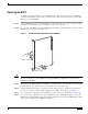
Replacing the RSP2
The RSP2 is keyed for installation only in an RSP slot. By default, the system active is the RSP that
occupies the first RSP slot in the router: slot 2 in the Cisco 7507, and slot 6 in the Cisco 7513. Follow
these steps to install an RSP2:
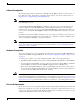
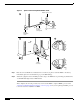
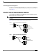
Step 1 Grasp the RSP2 handle with one hand and place your other hand under the carrier to support and guide
it into the slot. (See Figure 4.) Avoid touching the board or any connectors.
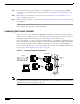
Step 2 Place the back of the RSP2 in the appropriate RSP slot and align the notches along the edge of the carrier
with the grooves in the slot. (See Figure 3a.)
Figure 4 Handling the RSP2 During Removal and Installation
Caution To prevent damage to the backplane, you must install the RSP2 in one of the two RSP slots on the router.
The slots are keyed for correct installation. Forcing the RSP2 into a different slot can damage the
backplane and the RSP2.
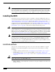
Step 3 While keeping the RSP2 parallel to the backplane, carefully slide the carrier into the slot until the RSP2
faceplate makes contact with the ejector levers, and then stop. (See Figure 3b.)
Step 4 Using the thumb and forefinger of each hand to pinch each ejector lever, simultaneously push both
ejector levers inward (toward the handle) until they are parallel to the faceplate. (See Figure 3c.)
Step 5 Use a screwdriver to tighten the captive installation screws on the ends of the RSP2. (See Figure 3a.)
Step 6 Use a screwdriver to tighten the two captive installation screws on the RSP2 faceplate to prevent the
RSP2 from becoming partially dislodged from the backplane and to ensure proper EMI shielding. (These
screws must be tightened to meet EMI specifications.)
H1355a