
Specifications

15
OL-4923-01 B0
• ESD-prevention equipment or the disposable ESD-preventive wrist strap included with all spares
and upgrade kits.
• Antistatic mat, foam pad, or bag for the removed RSP2 (place the removed RSP2 into an antistatic
bag if you plan to return it to the factory, or on an antistatic mat or foam if you are replacing
components and will reinstall the RSP2).
• DRAM SIMMs from Cisco if you are replacing SIMMs.
Removing the RSP2
When you remove or install the RSP2, be sure to use the ejector levers, which help to ensure that the
RSP2 is fully inserted in the backplane or fully dislodged from it. An RSP2 that is only partially
connected to the backplane can halt the system unless a second RSP2 is installed.
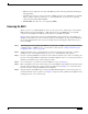
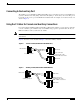
Figure 3 shows a detail of the ejector lever mechanism that is appropriate for the router. When you
simultaneously push the ejector levers inward (toward the carrier handle), the levers push the RSP2 into
the slot and ensure that the board connectors are fully seated in the backplane. Follow these steps to
remove the RSP2:
Step 1 Optional step: If you are replacing the RSP2 in a system with one RSP2, copy the currently running
configuration file to a TFTP server so you can retrieve it later. (See the “Saving and Retrieving the
Configuration File” section on page 66.)
Step 2 Attach an antistatic strap to yourself and then connect the equipment end of the strap to a captive
installation screw on an installed interface processor, or to any unfinished chassis surface.
Step 3 If you are replacing the RSP2, disconnect any devices that are attached to the console or auxiliary ports.
If you are removing the RSP2 for maintenance and will reinstall the same one, you can leave the devices
attached provided that doing so will not strain the cables.
Step 4 Use a screwdriver to loosen the two captive installation screws. (See Figure 3.)
Step 5 Place your thumbs on the ends of each of the ejectors and simultaneously pull them both outward, away
from the carrier handle (in the opposite direction from that shown in Figure 3c) to release the carrier
from the slot and to dislodge the RSP2 from the backplane.
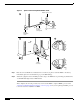
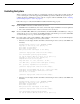
Step 6 Grasp the handle of the RSP2 with one hand and pull the RSP2 straight out of the slot, keeping your
other hand under the carrier to guide it. (See Figure 4.) Keep the carrier parallel to the backplane. Avoid
touching the board or any connector pins.