
Installation guide


Table Of Contents
- Overview of Cisco Interface Cards
- Cisco 3700 Series Routers
- Cisco 3600 Series Routers
- Cisco 2600 Series Routers
- Cisco 1700 Series Routers
- Cisco 1600 Series Routers
- Cisco ICS 7750
- Cisco MWR 1941-DC Router
- Regulatory Compliance Information and Safety
Chapter 1 Overview of Cisco Interface Cards
Cisco 3600 Series Routers
1-12
Cisco Interface Cards Installation Guide
OL-1919-12
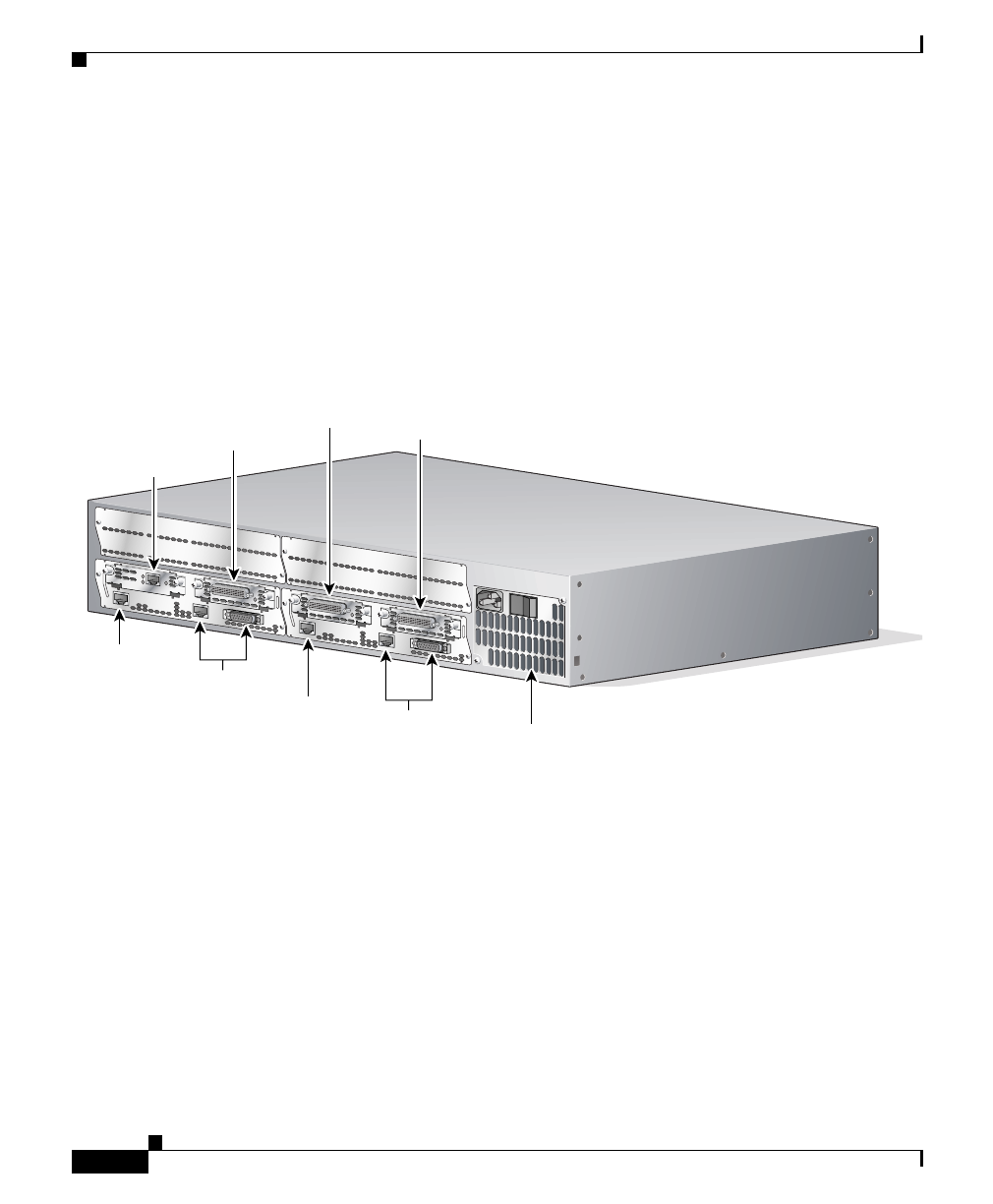
Figure 1-8 shows a router with a 2E 2-slot module in slots 0 and 1. Two serial
WAN interface cards are installed in the module in slot 0. One serial and one
ISDN BRI WAN interface card are installed in the module in slot 1.
Unit numbers identify the interfaces on the modules and interface cards installed
in the router. Unit numbers begin at 0 for each interface type, and continue from
right to left and (if necessary) from bottom to top. Modules and interface cards
are identified by interface type, slot number, followed by a forward slash (/), and
then the unit number; for example, Ethernet 0/0.
Figure 1-8 Cisco 3600 Series Unit Numbers
Voice Interface Numbering in Cisco 3600 Series Routers
Voice interfaces are numbered differently from WAN interfaces described in the
“Unit Numbering” section on page 1-11. Voice interfaces are shown as follows:
interface type chassis slot/voice module slot/voice interface
For example, Slot 1, voice network module slot 0, is referred to as voice 1/0/0
(closest to chassis slot 0).
3
1
2
INPUT 100-240VAC 50/60HZ 3.0-1.5 AMPS
ETHERNET 1
ETHERNET 0
2E
2W
W1
W0
ACT
ACT
LINK
AUI
EN
ETHERNET 1
ETHERNET 0
2E
2W
W1
W0
ACT
ACT
LINK
AUI
EN
ACT
SERIAL
ACT
SERIAL
ACT
SERIAL
LINK
SEE MANUAL BEFORE INSTALLATION
B1
B2
ACT
BRI
NT1
Power supply
BRI 1/0
Ethernet 1/0
Ethernet 0/1
Ethernet 0/0
Ethernet 1/1
Serial 1/0
Serial 0/1
Serial 0/0
41182