Prisma MediaCenter SNMP Management Module Installation Instructions Overview Introduction The Prisma® MediaCenter™ SNMP Management Module includes two twistedpair ports; one for management and one reserved for future use. The Management Module also features a DB-9 serial port. Both twisted pair ports include the AutoCross feature that automatically selects between a crossover workstation or straight-through, depending on the connected device.
Overview Only appropriately qualified and skilled personnel should attempt to install, operate, maintain, and service this product. Safety Instructions Refer to the applicable chassis guide for safety instructions. In This Document 2 Product Description....................................................................................................3 Module Installation ....................................................................................................
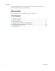
Product Description Product Description Module Front View The illustration below shows the front view of the SNMP Management Module. Module Front Panel Components LED Function LNK/ACT Glows green when a link is established on port. Glows yellow when one power supply malfunctions. FDX/COL TEMP PS FAN A / FAN B 4027869 Rev A Blinks green when data activity occurs. Glows yellow when port is in Full-Duplex mode. Blinks yellow when collisions occur.
Module Installation Module Installation Electrostatic Discharge Precautions Electrostatic discharge (ESD) can cause damage to the plug-in Media Converter modules that install into the chassis. Always observe the following precautions when installing or handling a module or any board assembly. 1 Do not remove the module from its protective packaging until you are ready to install it. 2 Wear an ESD wrist grounding strap before handling any module or component.
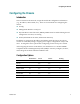
Configuring the Chassis Configuring the Chassis Introduction Once connected to the network, assign the module IP configuration information (e.g., IP address, subnet mask, etc.). There are four methods for configuring the chassis. iConfig Management Module’s serial port Dynamic Host Control Protocol (DHCP); DHCP must be enabled through serial configuration or Telnet, via iConfig Telnet (Default IP=10.10.10.10; subnet mask 255.0.0.
Configuring the Chassis SNMP Write Lock Switch There is an SNMP Write Lock switch located on the chassis. Check the specific chassis manual for the location. The SNMP Write Lock switch prevents a new Management Module from re-configuring the application module settings (e.g., the status of features such as LinkLoss, FiberAlert, Force mode, etc.) made via SNMP on any previous Management Module(s). Note: Leave this switch in the NORMAL position during day-to-day operation.
Configuring the Chassis 2 After configuring all application module settings via SNMP, use the iConfig application to make a backup copy of the SNMP management module's firmware. 3 If the SNMP management module needs to be replaced, set the SNMP Write Lock switch to LOCKED. 4 Remove the old SNMP module and replace with another SNMP module. 5 Connect to this SNMP module via PrismaView, then launch iConfig. 6 Select the Administration tab and click on List Tasks.
Configuring the Chassis Once the new IP address is received, the SNMP Management Module will reboot so that the new IP address will take effect. Refer to Serial Port Configuration (on page 9) for enable/disable information. If there is no DHCP server on the network, use iConfig or serial configuration to manually set the IP addresses. When DHCP is enabled, the default IP address (10.10.10.10) or the IP address assigned, is saved.
Configuring the Chassis Administrator Can perform all functions and add/delete accounts and perform the command cleandb. A Username and Password can be added in the USER tab of iConfig, or the Accounts command within Telnet or the Serial Configuration. Admin/admin should not be deleted until new usernames/passwords are tested. Passwords Passwords are a way to make the management of network devices secure.
Configuring the Chassis Saved Values — displays changes made during current session. - IP Address (MUST be assigned during initial configuration) - Subnet Mask (MUST be assigned during initial configuration) - Default Gateway Current Values — displays values currently in use.
Configuring the Chassis Main Serial/Telnet Configuration Screen Assigning TCP/IP Information Follow these steps to modify the Saved Values (i.e., assign IP address and subnet mask). 1 From the Main Configuration screen, press I. 2 Enter the IP address for the connected device and press Enter. 3 Enter the subnet mask for the connected device and press Enter. 4 If desired, assign a default gateway OR to skip, press Enter. 5 When finished, press Enter. 6 Type reboot for changes to take effect.
Configuring the Chassis R – read-only access W – read/write access Enter – abort 4 Press Enter. 5 Type reboot for changes to take effect. Result: The Saved Values and Current Values should now both display the changes made (e.g., new IP address and subnet mask). Deleting Community Strings Follow these steps to delete all community strings and start over. 1 From the Main Configuration screen, press U. 2 Press Y to proceed OR press N to abort. 3 Press Enter.
Configuring the Chassis Password Protection A password protects the serial configuration. Passwords are a way to make the management of network devices secure. If the password(s) are lost, neither the end user nor Administrator can retrieve it. Passwords are case sensitive and should be no more than eight characters in length with no spaces. This password will be requested whenever logging on or off. Adding Password Protection 1 From the Main Configuration screen, press P.
Configuring the Chassis Note: If the download is interrupted, do not reset the module or reboot the chassis. Close the session, and then open a new TFTP session. Additional Device-Specific Options Option Description tasks Displays the Task List along with each tasks’ priority. memory Displays the memory usage. cleandb Reboot with clean database. Result: This removes all information in the database except the IP address of device.
Using PrismaView Software for Management Using PrismaView Software for Management Introduction PrismaView software is a network management application for our intelligent networking devices. It features a graphical user interface (GUI) and gives network managers the ability to monitor and control products from a variety of platforms. PrismaView software can also function as a snap-in module for Hewlett-Packard’s (HP) OpenView Network Node Manager (NNM).
Installing and Using the PrismaView Software Installing and Using the PrismaView Software Introduction Consult the PrismaView CD for installation information. The Help tab in PrismaView provides assistance in configuring/managing modules. If Using PrismaView Software with HP OpenView NNM During the installation, PrismaView software will ask if HP OpenView NNM is installed on the management PC. Click Yes to integrate the appropriate files.
Installing and Using the PrismaView Software Update Manager Options Screen 4027869 Rev A 17
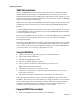
Unified Management Agent Unified Management Agent Centralized management makes practical sense for networks of all sizes, especially service provider networks that must monitor and upgrade large quantities of devices. The Unified Management Agent (UMA) allows operators to manage all modules with on-board logic (FiberLinX-II series) installed in a chassis, with a single IP address from a central location.
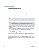
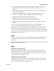
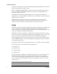
Unified Management Agent File Management for Upgrading The following screen, located in the iConfig utility of PrismaView, shows the File Management functionality of the UMA. Operators can easily upload and store new firmware versions for upgrading multiple devices with on-board logic installed in, or connected to, a chassis. Telnet Session with UMA With the UMA, users can also manage multiple devices installed in, or connected to, a chassis via a Telnet session, as well as assigning an IP address.
Unified Management Agent The FiberLinX-II series modules offer a new mode of saving a Configuration File, as well as a Restore File option. Refer to the appropriate manuals for complete information.
For Information For Information Support Telephone Numbers This table lists the Technical Support and Customer Service numbers for your area.
For Information Region Centers Telephone and Fax Numbers Mexico, Central America, Caribbean Mexico For Technical Support, call: Telephone: 52-3515152599 Fax: 52-3515152599 For Customer Service or to request an RMA number, call: Telephone: 52-55-50-81-8425 Fax: 52-55-52-61-0893 E-mail: karla.lugo@sciatl.
Scientific Atlanta, A Cisco Company 5030 Sugarloaf Parkway, Box 465447 Lawrenceville, GA 30044 678-277-1000 www.scientificatlanta.com Cisco, Cisco Systems, the Cisco logo, the Cisco Systems logo, Prisma, PrismaView, MediaCenter, SciCare, and Scientific Atlanta are registered trademarks or trademarks of Cisco Systems, Inc. and/or its affiliates in the U.S. and certain other countries. All other trademarks mentioned in this document are the property of their respective owners.