PA-FE-TX and PA-FE-FX Fast Ethernet 100BaseT Port Adapter Installation and Configuration Product Numbers: PA-FE-TX(=) and PA-FE-FX(=) Platforms Supported: Cisco 7200 Series, Cisco 7000 Series and Cisco 7500 Series with VIP2, Cisco uBR7200 Series, Cisco 7100 Series Note If you ordered this port adapter as a spare, for your convenience Cisco has included a port adapter installation and configuration note for the Catalyst 5000 series Route Switch Module/Versatile Interface Processor 2 (RSM/VIP2).
Access Registrar, AccessPath, Any to Any, AtmDirector, CCDA, CCDE, CCDP, CCIE, CCNA, CCNP, CCSI, CD-PAC, the Cisco logo, Cisco Certified Internetwork Expert logo, CiscoLink, the Cisco Management Connection logo, the Cisco NetWorks logo, the Cisco Powered Network logo, Cisco Systems Capital, the Cisco Systems Capital logo, Cisco Systems Networking Academy, the Cisco Technologies logo, ControlStream, Fast Step, FireRunner, GigaStack, IGX, JumpStart, Kernel Proxy, MGX, Natural Network Viewer, NetSonar, Network
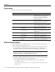
Preface This preface explains the objectives and organization of this document and how to find additional information on related products and services.
Organization Organization This document is organized into the following chapters: Section Title Description Chapter 1 Overview Provides information about the PA-FE-TX and PA-FE-FX 100BaseT port adapters, illustrates their location in the supported hardware platforms, and describes their LED displays, cables, and receptacles Chapter 2 Preparing for Installation Provides information about safety considerations, tools required, and procedures you should perform before the actual installation Chapter
Related Documentation • For hardware installation and maintenance information on Cisco 7100 series routers, refer to the Cisco 7100 Series VPN Router Installation and Configuration Guide publication that shipped with your Cisco 7100 series router. • For information on setting up a Virtual Private Network, see the Cisco 7100 Series VPN Configuration Guide.
Cisco Connection Online Cisco Connection Online Cisco Connection Online (CCO) is Cisco Systems’ primary, real-time support channel. Maintenance customers and partners can self-register on CCO to obtain additional information and services. Available 24 hours a day, 7 days a week, CCO provides a wealth of standard and value-added services to Cisco’s customers and business partners.
C H A P TER 1 Overview This chapter provides physical and functional overviews of the PA-FE-TX and PA-FE-FX Fast Ethernet 100BaseT port adapters. The chapter contains the following sections: • • • • • • Port Adapter Overview, page 1-1 Port Adapter Locations on the Supported Platforms, page 1-2 LEDs, page 1-5 Receptacles, Cables, and Pinouts, page 1-5 Fast Ethernet Overview, page 1-9 IEEE 802.
Port Adapter Locations on the Supported Platforms PA-FE-FX Port Adapter—Faceplate View TX RX R BE H6014 FI I NK FAST ETHERNET 0 MI LI EN AB LE D Figure 1-2 The PA-FE can be installed in the following slots on the hardware platforms described in this document: • • VIP2—Port adapter slot 0 and port adapter slot 1 • Cisco uBR7200 series universal broadband routers—Port adapter slot 1 and slot 2 of the Cisco uBR7246; port adapter slot 1 of the Cisco uBR7223 • Cisco 7100 series—Port adapte
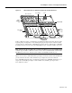
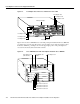
Port Adapter Locations on the Supported Platforms Figure 1-4 VIP2-50 with Two Port Adapters Installed—Horizontal Orientation Boot ROM CPU Bus connector SRAM daughter card Port adapter in slot 1 H10447 Port adapter in slot 0 DRAM DIMM In Cisco 7200 series routers, port adapter slots are numbered from the lower left to the upper right, beginning with port adapter slot 1 and continuing through port adapter slot 2 for the Cisco 7202, slot 4 for the Cisco 7204 and Cisco 7204VXR, and slot 6 for the Cisc
Port Adapter Locations on the Supported Platforms Figure 1-5 Port Adapter Slots in the Cisco 7200 Series—Cisco 7206 Port adapter slot 6 Port adapter slot 4 Port adapter slot 2 Blank port adapter 3 2 1 0 6 TOKEN RING 5 FAST ETHERNET 4 RJ4 5 MII 0 LIN K D LE AB EN 0 TX 2 RX 4 TX RX 3 TX RX 2 1 TX RX TX EN ETHERNET-10BFL CD LB RC RD TC TD CD LB RC RD TC TD CD LB RC RD TC TD CD LB RC RD TC TD EN FAST SERIAL RX 3 3 2 2 1 0 LINK 1 0 3 EN AB LE D E
LEDs LEDs The PA-FE-TX and the PA-FE-FX have an enabled LED, standard on all port adapters, and a bank of three status LEDs for the ports. After system initialization, the enabled LED goes on to indicate that the PA-FE has been enabled for operation. (The LEDs are shown in Figure 1-7.) LEDs on the PA-FE Port Adapter—Partial Faceplate View of PA-FE-TX H4710 Figure 1-7 The following conditions must be met before the enabled LED goes on: • • The PA-FE is correctly connected and receiving power.
Receptacles, Cables, and Pinouts Figure 1-8 shows the RJ-45 cable connectors. Cisco Systems does not supply Category 5 UTP RJ-45 cables; these cables are available commercially. Table 1-1 lists the pinouts and signals for the PA-FE-TX RJ-45 connectors. PA-FE-TX RJ-45 Connections—Plug and Receptacle H2936 Figure 1-8 87654321 RJ-45 connector Warning The ports labeled “Ethernet,” “10BaseT,” “Token Ring,” “Console,” and “AUX” are safety extra-low voltage (SELV) circuits.
Receptacles, Cables, and Pinouts Figure 1-10 Crossover Cable Pinout—PA-FE-TX RJ-45 Connections Between Hubs and Repeaters Hub or repeater 3 TxD+ 3 TxD+ 6 TxD– 6 TxD– 1 RxD+ 1 RxD+ 2 RxD– 2 RxD– H3138 Hub or repeater Figure 1-11 shows the duplex SC connector (one required for both transmit and receive), and Figure 1-12 shows the simplex SC connector (two required, one for each transmit and receive) used for PA-FE-FX optical-fiber connections.
Receptacles, Cables, and Pinouts Figure 1-13 PA-FE-TX or PA-FE-FX MII Connection—Receptacle H2943 Pin 21 Jackscrew Pin 1 Table 1-2 lists the MII connector pinout and signals. MII cables are available commercially and are not available from Cisco Systems. Table 1-2 refers to MII cables used between the MII connector on the PA-FE-TX and an appropriate transceiver. The connection between this transceiver and your network can be Category 3, 4, or 5, 150-ohm UTP or FTP, or multimode optical fiber.
Fast Ethernet Overview Fast Ethernet Overview The term Ethernet is commonly used for all carrier sense multiple access collision detect (CSMA/CD), LANs that generally conform to Ethernet specifications, including Fast Ethernet under IEEE 802.3u. Note 100BaseTX is intended for Environment A, and 100BaseFX is intended for Environment B. IEEE 802.3u is well suited to applications where a local communication medium must carry sporadic, occasionally heavy traffic at high peak data rates.
IEEE 802.3u 100BaseT Specifications IEEE 802.3u 100BaseT Specifications Table 1-3 lists the cabling specifications for 100-Mbps Fast Ethernet transmission over UTP, FTP, and fiber-optic cables. Table 1-4 summarizes IEEE 802.3u 100BaseT physical characteristics. Table 1-3 Specifications and Connection Limits for 100-Mbps Transmission Parameter RJ-45 1 2 MII SC-Type Cable specification Category 5 UTP , 22 to 24 AWG Category 3, 4, or 5, 150-ohm UTP or FTP, or multimode optical fiber 62.
C H A P TER 2 Preparing for Installation This chapter describes the general equipment, safety, and site preparation requirements for installing the PA-FE-TX and PA-FE-FX Fast Ethernet port adapters. The chapter contains the following sections: • • • • List of Parts and Tools, page 2-1 Software and Hardware Requirements, page 2-2 Safety Guidelines, page 2-3 FCC Class B Compliance, page 2-6 List of Parts and Tools You need the following tools and parts to install a port adapter.
Software and Hardware Requirements Software and Hardware Requirements Table 2-1 lists the minimum Cisco IOS software release required to use the PA-FE-TX and PA-FE-FX in supported router platforms. Table 2-1 PA-FE-TX and PA-FE-FX Software Requirements Router Platform Recommended Minimum Cisco IOS Release Cisco 7000 series and Cisco 7500 series • With VIP2-15(=) or VIP2-40(=) Cisco IOS Release 11.1(472) or a later release of Cisco IOS Release 11.1 Cisco IOS Release 11.
Safety Guidelines Caution The VIP2 requires that Cisco 7000 series routers have the RSP7000 and RSP7000CI installed. The VIP2 will not operate properly with the Route Processor (RP), Switch Processor (SP), or Silicon Switch Processor (SSP) installed in a Cisco 7000 series router. Safety Guidelines Following are safety guidelines that you should follow when working with any equipment that connects to electrical power or telephone wiring.
Safety Guidelines La traduzione delle avvertenze riportate in questa pubblicazione si trova nel documento Regulatory Compliance and Safety Information (Conformità alle norme e informazioni sulla sicurezza) che accompagna questo dispositivo. Advarsel Dette varselsymbolet betyr fare. Du befinner deg i en situasjon som kan føre til personskade.
Preventing Electrostatic Discharge Damage • Never touch uninsulated telephone wires or terminals unless the telephone line has been disconnected at the network interface. • Use caution when installing or modifying telephone lines. Preventing Electrostatic Discharge Damage Electrostatic discharge (ESD) damage, which can occur when electronic cards or components are improperly handled, can result in complete or intermittent failures.
FCC Class B Compliance FCC Class B Compliance The equipment described in this document generates and may radiate radio-frequency energy. If it is not installed in accordance with Cisco’s installation instructions, it may cause interference with radio and television reception. This equipment has been tested and found to comply with the limits for a Class B digital device in accordance with the specifications in part 15 of the FCC rules.
C H A P TER 3 VIP2 and the PA-FE Port Adapters This chapter provides information on the PA-FE-TX and the PA-FE-FX port adapters and their use in the VIP2 in Cisco 7000 series and Cisco 7500 series routers.
Installation Overview The PA-FE-TX and PA-FE-FX can be installed in either port adapter slot 0 or port adapter slot 1 on the VIP2. Figure 3-1 shows a PA-FE-TX installed in port adapter slot 0 on a VIP2-15 or VIP2-40. Figure 3-2 shows a PA-FE-FX installed in port adapter slot 0 on a VIP2-15 or VIP2-40.
Installation Overview Figure 3-2 VIP2-15 or VIP2-40 with a PA-FE-FX in Port Adapter Slot 0 Bus connector CPU Boot ROM U6 SRAM DIMM U5 U4 DRAM SIMMs U2 Port adapter blank in port adapter slot 1 ER H6453 II FIB M FAST ETHERNET 0 LIN K PA-FE-FX in portadapter slot 0 R BE FI NK LI MI I Port adapter handles not shown Figure 3-3 shows a PA-FE-TX installed in port adapter slot 0 on a VIP2-50. Figure 3-4 shows a PA-FE-FX installed in port adapter slot 0 on a VIP2-50.
Removing a Port Adapter Figure 3-4 VIP2-50 with an PA-FE-FX in Port Adapter Slot 0 Boot ROM CPU Bus connector SRAM daughter card DRAM DIMM R BE NK II FI LI 0 M FAST ETHERNET Handles not shown Removing a Port Adapter Use the following standard procedure to remove a port adapter from a VIP2: Step 1 Attach an ESD-preventive wrist strap between you and an unfinished chassis surface. Warning During this procedure, wear grounding wrist straps to avoid ESD damage to the card.
Removing a Port Adapter Step 4 Location of Port Adapter Screw—Partial Port Adapter H3148 Figure 3-5 Locate the screw at the rear of the port adapter (or blank port adapter) to be replaced. (See Figure 3-5.) This screw secures the port adapter (or blank port adapter) to its slot. Screw Step 5 Remove the screw that secures the port adapter (or blank port adapter).
Installing a Port Adapter Installing a Port Adapter Use the following standard procedure to install a port adapter on a VIP2: Step 1 Attach an ESD-preventive wrist strap between you and an unfinished chassis surface. Warning During this procedure, wear grounding wrist straps to avoid ESD damage to the card. Do not directly touch the backplane with your hand or any metal tool, or you could shock yourself.
Installing a Port Adapter Step 4 Carefully slide the new port adapter into the port adapter slot until the connector on the port adapter is completely seated in the connector on the motherboard. Step 5 Replace the screw in the rear of the port adapter slot. (See Figure 3-5 for its location.) Do not overtighten this screw. Step 6 Reinstall the VIP2 in the system.
Installing a Port Adapter 3-8 PA-FE-TX and PA-FE-FX Fast Ethernet 100BaseT Port Adapter Installation and Configuration
C H A P TER 4 Cisco 7200 Series and the PA-FE Port Adapters This chapter provides information on the PA-FE-TX and PA-FE-FX port adapters and their use in the Cisco 7200 series routers. This chapter contains the following sections: • • • Installation Overview, page 4-1 Removing a Port Adapter, page 4-2 Installing a Port Adapter, page 4-4 Note The Cisco 7206VXR and the Cisco 7206 can be used as router shelves in a Cisco AS5800 Universal Access Server.
Removing a Port Adapter Figure 4-1 Cisco 7206 with a PA-FE-TX in Slot 4 PA-FE-TX port adapter 3 2 1 5 0 6 TOKEN RING 5 4 K LIN 0 MII RJ4 EN AB LE D TX RX 3 4 2 TX RX TX RX 1 0 1 2 TX RX TX EN ETHERNET-10BFL CD LB RC RD TC TD CD LB RC RD TC TD CD LB RC RD TC TD CD LB RC TC RD EN FAST SERIAL TD FAST ETHERNET RX 3 2 3 LINK 1 0 2 1 EN 3 AB LE 0 D ETHERNET 10BT M II FE 0 II M N E SL O T EJ EC T PC M C IA EN AB LE D 0 H6786 SL O
Removing a Port Adapter Figure 4-3 Placing the Port Adapter Lever in the Unlocked Position—Cisco 7206 3 2 1 5 0 6 TOKEN RING FAST ETHERNET 4 RJ4 5 MII 0 LIN K D LE AB EN 3 2 3 LINK 1 0 2 1 0 EN 3 AB LE D ETHERNET 10BT 2 CD LB RC RD TC TD CD LB RC RD TC TD CD LB RC RD TC TD CD LB RC RD TC ET H6596 C 45 1O O PW K R 5 R E J4 N 5 R L J4 IN K M E II N T 0 EC O T EJ SL PC M C IA EN AB LE D 0 R J- FAST ETHERNET INPUT/OUTPUT CONTROLLER PU
Installing a Port Adapter Installing a Port Adapter Use the following procedure to install a new port adapter in a Cisco 7200 series router: Step 1 Attach an ESD-preventive wrist strap between you and an unfinished chassis surface. Warning During this procedure, wear grounding wrist straps to avoid ESD damage to the card. Do not directly touch the backplane with your hand or any metal tool, or you could shock yourself.
Installing a Port Adapter Figure 4-6 Placing the Port Adapter Lever in the Locked Position—Cisco 7206 3 2 1 5 0 6 TOKEN RING FAST ETHERNET 4 RJ4 5 MII 0 LIN K D LE AB EN 3 2 3 LINK 1 0 2 1 0 EN 3 AB LE D ETHERNET 10BT 2 CD LB RC RD TC TD CD LB RC RD TC TD CD LB RC RD TC TD CD LB RC RD TC ET 0 D LE AB O PW K R R E J4 N 5 1O R L J4 IN 5 K M E II N T 0 EC O T SL EJ PC M C IA EN H6747 C 45 R J- FAST ETHERNET INPUT/OUTPUT CONTROLLER PU R
Installing a Port Adapter 4-6 PA-FE-TX and PA-FE-FX Fast Ethernet 100BaseT Port Adapter Installation and Configuration
C H A P TER 5 Cisco uBR7200 Series and the PA-FE Port Adapters This chapter provides information on the PA-FE-TX and PA-FE-FX port adapters and their use in Cisco uBR7200 series universal broadband routers.
Removing a Port Adapter Figure 5-1 Cisco uBR7200 Series with a PA-FE-TX in Slot 2—Cisco uBR7246 H11503 PA-FE-TX port adapter Figure 5-2 shows a PA-FE-FX installed in slot 2 of a Cisco uBR7200 series router.
Removing a Port Adapter Figure 5-3 Placing the Port Adapter Retention Clip in the Unlocked Position—Cisco uBR7246 H11518 Port adapters Port adapter retention clip in unlocked position — For a Cisco uBR7223, place the port adapter lever in the unlocked position. (See Figure 5-4.
Installing a Port Adapter Caution Always handle the port adapter by the carrier edges and handle; never touch the port adapter’s components or connector pins. (See Figure 5-5.) Figure 5-5 Handling a Port Adapter Metal carrier H6420 Printed circuit board Step 6 Place the port adapter on an antistatic surface with its components facing upward, or in a static shielding bag. If the port adapter will be returned to the factory, immediately place it in a static shielding bag.
Installing a Port Adapter Figure 5-6 Aligning the Port Adapter Metal Carrier Between the Slot Guides Metal carrier H11519 Inside slot guide PC board Step 4 With the metal carrier aligned in the slot guides, gently slide the port adapter halfway into the slot. Caution Do not slide the port adapter all the way into the slot until you have connected all required cables. Trying to do so disrupts normal operation of the router.
Installing a Port Adapter Figure 5-7 Placing the Port Adapter Retention Clip in the Locked Position—Cisco uBR7246 H11517 Port adapters Port adapter retention clip in locked position For a Cisco uBR7223, place the port adapter lever in the locked position. (See Figure 5-8.
C H A P TER 6 Cisco 7100 Series and the PA-FE-TX and PA-FE-FX This chapter provides information on the PA-FE-TX and PA-FE-FX port adapters and their use in Cisco 7100 series routers. This chapter contains the following sections: • • • Installation Overview, page 6-1 Removing a Port Adapter, page 6-2 Installing a Port Adapter, page 6-3 Installation Overview The PA-FE-TX and PA-FE-FX can be installed in port adapter slot 3 in the Cisco 7120 series and in port adapter slot 4 in the Cisco 7140 series.
Removing a Port Adapter Figure 6-2 Cisco 7140 series Router—Port Adapter Slot 4 Location Locked Unlocked ESD plug Slot 4 AC OK DC OK OTF SLOT 0 SLOT 1 PWR ACT ACT 0 FE 0 / 0 I EN RX RX 155 - MM TX EN CEL CAR ALM FE 0 / 1 RX LNK LNK 0 1 RX 155 - MM CONS AUX AC OK SYS RDY DC OK OTF TX CEL CAR ALM 2 7140 - 2MM3 22134 5 Depending on your circumstances, you might need to install a new port adapter in a Cisco 7100 series router or replace a failed port adapter in the field.
Installing a Port Adapter Caution Always handle the port adapter by the carrier edges and handle; never touch the port adapter’s components or connector pins. (See Figure 6-3.) Figure 6-3 Handling a Port Adapter Metal carrier H6420 Printed circuit board Step 6 Place the port adapter on an antistatic surface with its components facing upward, or in a static shielding bag. If the port adapter will be returned to the factory, immediately place it in a static shielding bag.
Installing a Port Adapter Caution Do not slide the port adapter all the way into the slot until you have connected all required cables. Trying to do so disrupts normal operation of the router. Figure 6-4 Aligning the Single-Width Port Adapter Between the Slot Guides Guides I RCVR EN XMTR RCLK FERF RL FE 0 / 22132 5 AIS OOF LL Step 7 With the port adapter halfway in the slot, connect all required cables to the port adapter.
C H A P TER 7 Installing PA-FE Port Adapter Interface Cables To continue your PA-FE-TX and PA-FE-FX port adapter installation, you must install the port adapter’s interface cables. The following instructions apply to all supported platforms.
Attaching PA-FE Port Adapter Interface Cables Note Each PA-FE-FX or PA-FE-TX can have either an MII attachment or an RJ-45 (or SC) attachment, but not both simultaneously. The MII and RJ-45 (or SC) receptacles represent two physical connection options for one Fast Ethernet interface.
Attaching PA-FE Port Adapter Interface Cables Step 2 For the PA-FE-TX, attach the ferrite bead to the RJ-45 cable (at either end), as shown in Figure 7-3. Caution The ferrite bead prevents electromagnetic interference (EMI) from affecting the PA-FE-TX-equipped system and is a required component for proper system operation.
Attaching PA-FE Port Adapter Interface Cables 7-4 PA-FE-TX and PA-FE-FX Fast Ethernet 100BaseT Port Adapter Installation and Configuration
C H A P TER 8 Configuring PA-FE Port Adapter Interfaces To continue your PA-FE-TX and PA-FE-FX port adapter installation, you must configure the PA-FE-TX and PA-FE-FX interfaces. The following instructions apply to all supported platforms. Minor differences between the platforms are noted.
Using the EXEC Command Interpreter Using the EXEC Command Interpreter You modify the configuration of your router through the software command interpreter called the EXEC. You must enter the privileged level of the EXEC command interpreter (also called enable mode) with the enable command before you can use the configure command to configure a new interface or to change the existing configuration of an interface. The system prompts you for a password if one has been set.
Note For the Cisco 7206VXR and Cisco 7206 router shelves, physical port addresses are composed of a three-part number in the format shelf number/port adapter slot number/interface port number, where the shelf number is a number assigned to the router shelf during the initial configuration of the Cisco AS5800 Universal Access Server. A Cisco AS5800 Universal Access Server can consist of several shelves; therefore, each shelf is assigned a shelf number.
Identifying Chassis Slot, Port Adapter Slot, and PA-FE Interface Port Numbers The individual interface port numbers always begin with 0. The number of additional ports depends on the number of ports on a port adapter. For example, if the PA-FE in slot 4 (with the interface address 4/0 [port adapter slot 4, and interface port 0]) were in slot 2, the port adapter’s interface would be numbered 2/0.
Note Although the processor slots in the seven-slot Cisco 7000 and Cisco 7507 and thirteen-slot Cisco 7513 are vertically oriented and those in the five-slot Cisco 7010 and Cisco 7505 are horizontally oriented, all models use the same method for slot and port numbering. Interface ports on the VIP2 maintain the same address regardless of whether other interface processors are installed or removed.
Performing a Basic Configuration Figure 8-4 Port Adapter Slot Numbering—Cisco 7120 Series Slot 3 Slot 5 SLOT 0 SLOT 1 PWR ACT ACT 0 5 FE 0 / 0 EN TX LNK LNK 1 0/1 0 CONS AUX SYS RDY RX RX 18498 I E3 FE 2 CEL CAR ALM 7120 - AE3 Slot 1 Slot 0 Slots in the Cisco 7140 series are numbered as shown Figure 8-5. The fixed LAN interface is slot 0, the fixed WAN interfaces are slots 1 and 2, and the modular port adapter interface is slot 4. Slot 3 is not used. Slot 5 is the service adapter.
Use the following sample basic configuration procedure: Step 1 At the privileged-level prompt, enter configuration mode and specify that the console terminal is the source of the configuration subcommands, as follows: Router# configure terminal Enter configuration commands, one per line. Router(config)# Step 2 End with CNTL/Z.
Performing a Basic Configuration Configuring PA-FE Transmission Mode Half-duplex operation is the default transmission mode for the PA-FE. Use the full-duplex command to configure full-duplex operation for the PA-FE as follows: Router# configure terminal Enter configuration commands, one per line. Router(config)# Router(config)# interface fastethernet 4/0 Router(config-if)# full-duplex Ctrl-z End with CNTL/Z.
To check the interface configuration using show commands, proceed to the “Checking the Configuration” section on page 8-9. Checking the Configuration After configuring the new interface, use the show commands to display the status of the new interface or all interfaces and the ping command to check connectivity. Using show Commands to Verify the New Interface Status The following steps use show commands to verify that the new interfaces are configured and operating correctly.
Checking the Configuration If the interface is down and you configured it as up, or if the displays indicate that the hardware is not functioning properly, ensure that the network interface is properly connected and terminated. If you still have problems bringing the interface up, contact a service representative for assistance.
cisco 7200 (R4700) processor with 22528K/10240K bytes of memory. R4700 processor, Implementation 33, Revision 1.0 (Level 2 Cache) Last reset from power-on Bridging software. X.25 software, Version 2.0, NET2, BFE and GOSIP compliant. Chassis Interface. 4 Ethernet/IEEE 802.3 interfaces. 2 FastEthernet/IEEE 802.3 interfaces. 125K bytes of non-volatile configuration memory. 20480K bytes of Flash PCMCIA card at slot 0 (Sector size 128K). 8192K bytes of Flash internal SIMM (Sector size 256K).
Checking the Configuration VIP2 Show Commands Use the show interfaces type slot/port-adapter/port command, with arguments such as the interface type (fastethernet, and so forth) and the port number (slot/port), to display information about a specific interface only.
Use the show diagbus slot command to determine which type of port adapter is installed on a VIP2 in your system. Specific port adapter information is displayed, as shown in the following example of a PA-FE-FX in interface processor slot 1: Router# show diagbus 1 Slot 1: Physical slot 1, ~physical slot 0xE, logical slot 1, CBus 0 Microcode Status 0xC Master Enable, LED, WCS Loaded Board is analyzed Pending I/O Status: Console I/O EEPROM format version 1 VIP2 controller, HW rev 2.
Checking the Configuration Following is an example of a successful ping command to a remote server with the address 172.16.0.0: Router# ping 172.16.0.0 Type escape sequence to abort. Sending 5, 100-byte ICMP Echoes to 10.0.0.0, timeout is 2 seconds: !!!!! Success rate is 100 percent (5/5), round-trip min/avg/max = 1/15/64 ms Router# If the connection fails, verify that you have the correct IP address for the destination and that the device is active (powered on), and repeat the ping command.