C H A P T E R 1 Product Overview This chapter describes the Cisco 7600 series Internet Routers, supervisor engines, Optical Services Modules (OSMs), and recommended Catalyst 6000 family modules, and it contains these sections: • Cisco 7600 Series Internet Routers, page 1-1 • Supervisor Engines, page 1-6 • Optical Services Modules, page 1-14 • Catalyst 6000 Family Modules, page 1-25 • Port Addresses, page 1-31 • Hot Swapping Supervisor Engines and Modules, page 1-33 • Power Management and Envi
Chapter 1 Product Overview Cisco 7600 Series Internet Routers Cisco 7600 series Internet Routers provide optical WAN and MAN networking with a focus on line-rate delivery of high-touch IP services at the edge of service providers networks.
Chapter 1 Product Overview Cisco 7600 Series Internet Routers – Five additional modules for the Cisco 7606 Internet Router – Eight additional modules for the Cisco 7609 Internet Router – Twelve additional modules for the Cisco 7613 Internet Router • Hot-swappable fan assembly, redundant AC-input or DC-input power supplies, and modules. • Redundant AC-input or DC-input power entry modules (PEMs) (Cisco 7603 and 7606 Internet Routers only).
Chapter 1 Product Overview Cisco 7600 Series Internet Routers Table 1-1 Cisco 7600 Series Internet Router Key Features Feature Description Performance and configuration Refer to the Cisco 7600 Series Internet Router Software Configuration Guide for detailed information about the features supported on the Cisco 7600 series Internet Router.
Chapter 1 Product Overview Cisco 7600 Series Internet Routers Table 1-1 Cisco 7600 Series Internet Router Key Features (continued) Feature Memory components Description • 512-KB NVRAM stores configuration information. • EEPROM2 component on the supervisor engine stores module-specific information, such as the module serial number, part number, controller type, hardware revision, configuration information, and other details unique to each module. • 256-MB DRAM for the default system software.
Chapter 1 Product Overview Supervisor Engines Supervisor Engines Note The Supervisor Engine 1A is supported only on the Cisco 7603 Internet Router. Note The Supervisor Engine 720 is supported only on the Cisco 7609 Internet Router. This section describes the features on the Supervisor Engine 1A, Supervisor Engine 2, and Supervisor Engine 720.
Chapter 1 Product Overview Supervisor Engines Table 1-2 lists the supervisor engine configurations.
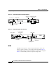
Chapter 1 Product Overview Supervisor Engines Figure 1-2 Supervisor Engine 2 Front Panel Features Console port Switch load 1000BASE-X GBIC display Uplink Ports PCMCIA LED WS-X6K-SUP2-2GE PCMCIA EJECT PORT 2 1% LIN K Status LEDs Console port mode switch PCMCIA slot 44312 ET ES CONSOLE SUPERVISOR2 LIN K LE G PORT 1 R S EM M R PW U SO N ST AT O C SY ST Load M T Switch 100% CONSOLE PORT MODE LINK LEDs Reset button Figure 1-3 Supervisor Engine 720 Front Panel CompactFl
Chapter 1 Product Overview Supervisor Engines Table 1-3 Supervisor Engines 1A and 2 LEDs LED Color Description STATUS Orange The module is booting or running diagnostics (normal initialization sequence). An overtemperature condition has occurred. (A minor threshold has been exceeded during environmental monitoring.) Green All diagnostics pass; the module is operational (normal initialization sequence). Red Diagnostic test failed; the module is not operational.
Chapter 1 Product Overview Supervisor Engines Table 1-3 Supervisor Engines 1A and 2 LEDs (continued) LED Color Description LINK Orange The link has been disabled by software. Flashing orange The link is bad and has been disabled due to a hardware failure. Green The port is operational. Off No signal is detected. 1. The SYSTEM and PWR MGMT LED indications on a redundant supervisor engine are synchronized to the active supervisor engine. 2. VTT = voltage termination module.
Chapter 1 Product Overview Supervisor Engines Table 1-4 Supervisor Engine 720 LEDs (continued) LED Color Description Orange The module is powering up or has minor hardware problems. Red Major hardware problem. Green Sufficient power is available for all modules. Orange The port is disabled. Flashing orange The port is bad. Green The port is operational. Off The module is powering up or the port is enabled and there is no link. DISK 0 Green The disk is active.
Chapter 1 Product Overview Supervisor Engines Note EIA/TIA-232 and EIA/TIA-449 were known as recommended standards RS-232 and RS-449 before their acceptance as standards by the Electronic Industries Alliance (EIA) and Telecommunications Industry Association (TIA). For detailed information on using this port, see the “Connecting to the Console Port” section on page 3-15.
Chapter 1 Product Overview Supervisor Engines Switch Load Meter The switch load meter provides you with a visual approximation of the current traffic load across the backplane. PCMCIA Slot The Flash PC card (PCMCIA card) slot holds a Flash PC card for additional Flash memory. You can use this Flash memory to store and run software images or to serve as an I/O device. Note Throughout this publication, the term Flash PC card is used in place of the term PCMCIA card.
Chapter 1 Product Overview Optical Services Modules Optical Services Modules This section describes the Optical Services Modules (OSMs).
Chapter 1 Product Overview Optical Services Modules Four, eight, or sixteen MT-RJ fiber ports providing full-duplex operation at 155 Mbps per port. (Half-duplex operation is not supported.
Chapter 1 Product Overview Optical Services Modules The 2-port (see Figure 1-7) and 4-port (see Figure 1-8) OC-12 POS OSMs provide the following: Standards-compliant SONET/SDH interface; SONET/STS-12c and SDH/STM-4c framing and signaling overhead. • Two or four SC fiber ports providing full-duplex operation at 622 Mbps per port. (Half-duplex operation is not supported.
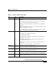
Chapter 1 Product Overview Optical Services Modules Figure 1-9 1-Port OC-48 POS OSM TX R X 45165 R X ET C AR AL RIE AR R M R ES LIN K 4 LIN K 3 LIN K 1 2 LIN K 1 PORT OC-48 POS SM SR 4 2 ST AT U S TX 1 3 AC TIV E OSM-1OC48-POS-SS OC-48 DPT/POS Table 1-8 lists the 2-port OC-48 DPT(dynamic port transport)/POS OSMs.
Chapter 1 Product Overview Optical Services Modules The CLI allows SDH framing and channel mappings although these configurations are not supported currently. Do not configure the channelized OC-12 modules for SDH framing. Note The 1-port (see Figure 1-11) channelized OC-12 OSMs support channelized configurations down to OC-3 and DS3. The channelized OC-12 modules can be configured as multiple OC-3 or DS3 channelized interfaces, or a mix of OC-3, DS3, and DS3 subrate channelized interfaces.
Chapter 1 Product Overview Optical Services Modules Figure 1-12 2-Port OC-12 ATM OSM E TX TX R X AC TIV TX R X 45160 2 R X C AR AL RIE AR R M 1 PO R T PO R T AC TIV R X C AR AL RIE AR R M 4 LIN K 4 3 LIN K 1 2 LIN K 2 PORT OC-12 ATM SM IR LIN K 2 ST R ES AT ET U S TX 3 1 E OSM-20C12-ATM-SI Gigabit Ethernet WAN Services Module The OSM-4GE-WAN-GBIC is the Gigabit Ethernet WAN Services Module.
Chapter 1 Product Overview Optical Services Modules 85345 Figure 1-14 2+4-Port Gigabit Ethernet WAN Services Module 12-Port Channelized T-3 The OSM-12CT3/T1 (Figure 1-15) can accept both clear-channel T3 trafficand multiplexed circuits from T1/E1 and DS0. Service features include support for IP and MPLS traffic, Class-Based Weighted Fair Queuing (CBWFQ), Low-Latency Queuing (LLQ), and Weighted Random Early Detection (WRED).
Chapter 1 Product Overview Optical Services Modules OSM STATUS LED The STATUS LED on all OSMs (see Figure 1-16) provides module status as shown in Table 1-11. Figure 1-16 OSM STATUS and LINK LEDs—Gigabit Ethernet Ports 45166 K 4 LI 3 N K 4 N LI K 2 LI N K 1 LI N 4 PORT OC-12 POS MM 2 ST AT U S 3 1 OSM-4OC12-POS-MM Table 1-11 OSM STATUS LED Description LED Color STATUS Normal initialization sequence Fault during initialization sequence Description Indicates module status.
Chapter 1 Product Overview Optical Services Modules Table 1-11 OSM STATUS LED Description (continued) LED Environmental monitoring Color Description Orange Overtemperature condition (minor threshold exceeded). Red Overtemperature condition (major threshold exceeded). Gigabit Ethernet Link LED Description The GBIC-based Gigabit Ethernet LINK LEDs (see Figure 1-16) are described in Table 1-12. Table 1-12 Module LINK LED Descriptions LED Color LINK n Description Indicates port and link status.
Chapter 1 Product Overview Optical Services Modules VE X R X 58944 4 C AR AL RI AR ER M R C AR AL RI AR ER M 3 TX TI AC X R TX VE TX AC TI TX R X Figure 1-17 LC OSM Interface LEDs 55749 T4 R PO C AR AL RI AR ER M R X TX AC R TX X TI VE Figure 1-18 SC OSM Interface LEDs Table 1-13 LC and SC Interface LED Descriptions LED Color ACTIVE CARRIER ALARM Description Indicates that the port has been configured and enabled.
Chapter 1 Product Overview Optical Services Modules Table 1-13 LC and SC Interface LED Descriptions (continued) LED Color Description Off The port is not active or transmitting data on the SONET link. RX Indicates that the port is active and receiving data from the SONET link. Green The port is active and receiving data from the SONET link. Off The port is not active or receiving data from the SONET link.
Chapter 1 Product Overview Catalyst 6000 Family Modules Table 1-14 MT-RJ OSM Interface LED Descriptions (continued) LED CARRIER ALARM Color Description Indicates that the port detects a valid SONET signal. Green A valid SONET signal has been detected with no alarm conditions. Yellow A valid SONET signal has been detected, but there are alarm conditions present (such as LRFI, PRFI, LOS, LOF, LOP, LAIS, PAIS, or Signal Label Mismatch). Off No valid SONET signal is detected.
Chapter 1 Product Overview Catalyst 6000 Family Modules FlexWAN Module (WS-X6182-2PA) Note The FlexWAN module is not fabric-enabled. When a Switch Fabric Module is installed in the Cisco 7600 series Internet Router, and there is a mix of fabric-enabled and non-fabric-enabled (classic) modules in the system, the central forwarding performance remains at 15 Mpps.
Chapter 1 Product Overview Catalyst 6000 Family Modules 48-Port 10/100TX Switching Module (WS-X6348-RJ-45) The 48-port 10/100TX switching module (WS-X6348-RJ-45), shown in Figure 1-21, provides 48 switched, 10/100-Mbps autosensing, full- or half-duplex ports. Ports have RJ-45 connectors for either Category 3 or Category 5 unshielded twisted-pair (UTP) cable.
Chapter 1 Product Overview Catalyst 6000 Family Modules Switch Fabric Module (WS-C6500-SFM) Note The Switch Fabric Module is not supported on the Cisco 7603 Internet Router. The Switch Fabric Module (WS-C6500-SFM), shown in Figure 1-23,requires Supervisor Engine 2 and must be installed in slots 5 or 6 of the Cisco 7600 series Internet Router. For redundancy, you can install a second Switch Fabric Module. The Switch Fabric Module that is installed first functions as the primary module.
Chapter 1 Product Overview Catalyst 6000 Family Modules • NEXT—Use this push button switch to scroll to the next item on the LCD display menu. Switch Fabric Module 2 (WS-X6500-SFM2) Note The Switch Fabric Module 2 is not supported on the Cisco 7603 Internet Router. The Switch Fabric Module 2 (WS-X6500-SFM2), shown in Figure 1-24, requires a Supervisor Engine 2 and must be installed in slots 5 or 6 of the Cisco 7600 series Internet Router. For redundancy, you can install a second Switch Fabric Module 2.
Chapter 1 Product Overview Catalyst 6000 Family Modules The front panel on the Switch Fabric Module 2 has a 2-line by 20-character LCD display. The display allows you to monitor the module’s input/outport port traffic and local bus traffic. The display also displays system information. Two push buttons are used with the LCD display: • SELECT—Use this push button switch for LCD display menu selection. • NEXT—Use this push button switch to scroll to the next item on the LCD display menu.
Chapter 1 Product Overview Port Addresses Table 1-15 Catalyst 6000 Family Module LEDs (continued) LED Color Description LINK Green The port is active (link connected and operational). Orange The module or port is disabled through the CLI command or the module is initializing2. Flashing orange The port is faulty and has been disabled. Off The port is not active or the link is not connected. 1. CLI = command-line interface. 2. This is a good time to verify that all LINK LEDs are functioning.
Chapter 1 Product Overview Port Addresses Physical Interface Addresses Physical port addresses specify the actual physical location of each module port on the rear of the router, as shown in Figure 1-25. (The port numbering convention is the same in the three-slot, six-slot, and nine-slot chassis.) The address is a two-part number in the format slot/port number. The first number identifies the slot in which the module is installed. Module slots are numbered from right to left starting with 1.
Chapter 1 Product Overview Hot Swapping Supervisor Engines and Modules Interface ports maintain the same address regardless of whether other modules are installed or removed. However, when you move a module to a different slot, the first number in the address changes to reflect the new slot number. For example, on a 4-port OC-12c POS OSM in slot 4 of the Cisco 7609 Internet Router, the address of the top WAN port is 4/1, and the address of the bottom WAN port is 4/4.
Chapter 1 Product Overview Hot Swapping Supervisor Engines and Modules Note Although the FlexWAN module supports hot swapping, individual port adapters do not. To replace port adapters, you must first remove the FlexWAN module from the chassis and then replace port adapters as required. When you remove or insert a module while the router is powered on and operating, the system does the following: 1. Determines if there is sufficient power for the module. 2.
Chapter 1 Product Overview Power Management and Environmental Monitoring Power Management and Environmental Monitoring For detailed information on power management and environmental monitoring, refer to the Cisco 7600 Series Internet Router Software Configuration Guide.
Chapter 1 Product Overview OSM Technology Overview SONET1 SDH Equivalent STS-3c STM-1 STS-12c STM-4c STS-48c STM-16c 1. ANSI-defined SONET specifications SONET is not limited to optical links. Electrical specifications have been defined for single-mode fiber, multimode fiber, and CATV 75-ohm coaxial cable. OSMs currently allow transmission only over single-mode and multimode optical fiber. Transmission rates are integral multiples of 51.