
Troubleshooting guide


9-11
Cisco Broadband Local Integrated Services Solution Troubleshooting Guide
OL-5169-01
Chapter 9 Troubleshooting Cisco Media Gateways
Troubleshooting Alarms
AXSM Card Controls
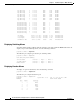
Figure 9-5 shows the LEDs available on the front of the AXSM card. Table 9-3 describes these LEDs.
Figure 9-5 AXSM Card Controls (MGX-AXSM-16-T3E3)
38656
CNTLR Port
CR
MJ
MN
DC-A
DC-B
ACO
HIST
ENET
ACO
HIST
SYSTEM
STATUS
PXM45/B
Critical alarm (blue)
Controller port
Major alarm (red)
Minor alarm (yellow)
System status
DC power A (green)
DC power B (green)
Alarm cut-off (yellow)
History (green)
Ethernet LAN control port (green)
Alarm cut-off
History
Green = active
Red = major alarm
Yellow = minor alarm
Blinking green = active
Slow blink yellow = standby
Fast blink yellow = boot
Solid red = reset, failure, or missing back card
Blinking red = software download