
Troubleshooting guide


5-15
Cisco Broadband Local Integrated Services Solution Troubleshooting Guide
OL-5169-01
Chapter 5 Troubleshooting DOCSIS Networks
Measuring RF Signals
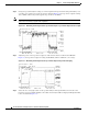
Figure 5-8 Measuring the RF Signal at the Upconverter Output---Output Adjusted to Correct Range
Note Any channel frequency response problems at the headend can impair network performance or prevent a
cable modem on the HFC network from operating. The specified maximum peak-to-valley measurement
from a Cisco cable modem card is +/-1.5 dB across 5.6 MHz. At the output of the upconverter, the
maximum tilt should not exceed +/-1.5 dB across 5.6 MHz. If the tilt is greater than +/-1.5 dB across 5.6
MHz when measured, the upconverter might not be compatible with digital QAM signals, or the
upconverter might be defective. Remember, however, that when using your spectrum analyzer in “video
averaging” mode, amplitude accuracy adjustments must also be taken into consideration.
Step 7 Verify that your headend RF measurements match the recommended settings listed in Table 5-2,
RF Specifications. Make a copy of the table and record your headend settings in the last column as you
verify them. This will assist in troubleshooting the Cisco uBR7246VXR installation later in the process.
Comparing Measurements to Recommended Settings
The following tables display recommended settings to which you can compare your downstream
measurements. Table 5-1 displays typical RF downstream modulation; and Table 5-2 displays DOCSIS
cable downstream RF specifications.
Table 5-1 Typical RF Downstream Modulation
Downstream Bandwidth 64 QAM Data Throughput 256 QAM Data Throughput
6 MHz 27.0 Mbs 38.0 Mbs
8 MHz 27.0 Mbs 38.0 Mbs