
Troubleshooting guide


5-14
Cisco Broadband Local Integrated Services Solution Troubleshooting Guide
OL-5169-01
Chapter 5 Troubleshooting DOCSIS Networks
Measuring RF Signals
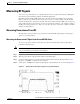
Step 4 Change the spectrum analyzer settings to view the digital channel power. This setting will enable you to
see if there is too much power on the upconverter output. In Figure 5-6, the upconverter output is reading
+64.31 dBmV, which is beyond the typical range of +50 to +58 dBmV.
Note A spectrum analyzer might become overloaded and produce false readings (such as internally generated
spurs) when measuring a signal at this amplitude.
Figure 5-6 Measuring the RF Signal at the Upconverter Output---Upconverter Output Level Too High
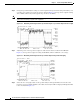
Step 5
Adjust the power on the upconverter output to ensure that it is between +50 and +58 dBmV. In
Figure 5-7, the upconverter output is reading +57.06 dBmV, which is within the correct range.
Figure 5-7 Measuring the RF Signal at the Upconverter Output Using Video Averaging
Step 6
Select the video averaging feature on the spectrum analyzer. The signal will become smoother and
frequency response problems might become visible. Your analyzer will now display an RF signal similar
to the one shown in Figure 5-8.