
Troubleshooting guide


5-13
Cisco Broadband Local Integrated Services Solution Troubleshooting Guide
OL-5169-01
Chapter 5 Troubleshooting DOCSIS Networks
Measuring RF Signals
Measuring the Downstream RF Signal at the Upconverter Output
To measure the downstream radio frequency (RF) signal, perform the following steps:
Step 1 Disconnect the spectrum analyzer from the cable modem card downstream connector. Connect the
downstream output of the cable modem card to the upconverter input connector. Connect the spectrum
analyzer to the RF output of the upconverter.
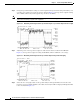
If your spectrum analyzer input is overloaded, you might see artifacts that are internally generated by
the spectrum analyzer. The artifacts are circled on the analyzer trace shown in Figure 5-4. The sloping
of the lines at the sides of the signal indicates a false reading.
Add attenuation to the input to the spectrum analyzer as necessary to correct the overload condition.
Figure 5-4 Overloaded Spectrum Analyzer Input
Step 2
Set the input of the upconverter to a digital QAM signal and the output level to the manufacturer's
recommended settings. Typical output amplitudes range from +50 to +58 dBmV.
Step 3 Set the spectrum analyzer to view the RF signal at the center frequency you selected for your headend.
In this example, the RF center frequency is 699 MHz. Set your span to 20 MHz. Finally, set your channel
spacing and your channel bandwidth to 6 MHz. If you still have an overload condition, similar to that
shown in Figure 5-4, add more attenuation to the input of the spectrum analyzer.
Figure 5-5 Measuring the RF Signal at the Upconverter ---Overload Corrected with Attenuation