
Troubleshooting guide


5-11
Cisco Broadband Local Integrated Services Solution Troubleshooting Guide
OL-5169-01
Chapter 5 Troubleshooting DOCSIS Networks
Measuring RF Signals
Measuring RF Signals
You can use a spectrum analyzer or a digital signal level meter to gather measurements of RF signals
that can help you in identifying problems and making adjustments.
Measuring downstream IF and RF signals with a spectrum analyzer is normally done at setup time.
However, if there are problems detected, it may be necessary to verify the quality of the IF and RF
downstream signals. For example, it is possible, that after the initial setup, the uBR or upconverter may
start to drift in frequency (because there is some sort of hardware problem), or the output level (that is,
the RF power being produced) is too high or too low. The only way to verify these conditions would be
with the spectrum analyzer.
Measuring Downstream IF and RF
The following sections describe how to measure the downstream RF signal using the channel power
option on a spectrum analyzer.
Measuring the Downstream IF Signal at the Cisco uBR7200 Series
To connect a spectrum analyzer and measure the downstream intermediate frequency (IF) signal,
perform the following steps:
Note Refer to the user guide that accompanied your spectrum analyzer to determine the exact steps required
to use your analyzer to perform these measurements.
Step 1 Connect a spectrum analyzer to the downstream connector on a cable modem card in a Cisco uBR7246.
Step 2 Turn the power switch on the spectrum analyzer to the ON position.
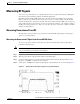
Step 3 Set the spectrum analyzer to view the downstream intermediate frequency (IF) signal with a center
frequency of 44 MHz for a North American headend.
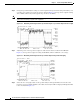
Step 4 Set the span to 10 MHz. Your analyzer should display a signal similar to the one shown in Figure 5-1.
Figure 5-1 Viewing the Downstream IF Signal on a Spectrum Analyzer