
Troubleshooting guide


5-9
Cisco Broadband Local Integrated Services Solution Troubleshooting Guide
OL-5169-01
Chapter 5 Troubleshooting DOCSIS Networks
Radio Frequency (RF) Issues
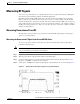
Operational State
MAC State --->>> 'operational_state' cmWriteFlashFile("CM_BOOT", 0x8109180, 0x13e) by TID
0x83049b8 (tMACCtrl)
usrEraseSysFlash(1, 0x1e0900, 0x13e) by TID 0x83049b8 (tMACCtrl)
If registration and baseline privacy negotiation (if required) succeed, the modem is operational and is
ready to pass traffic.
A modem may make it to operational state but not remain in operational state. This could be caused by
sync loss or DHCP lease renewal failure, just to name a couple.
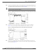
Radio Frequency (RF) Issues
Two-way digital data signals are more susceptible than one-way signals to stresses in the condition of
the HFC network. Degradation in video signal quality might not be noticed, but when two-way digital
signals share the network with video signals, digital signals might be hampered by the following types
of network variations:
• Impulse and electrical signal ingress---Noise can enter the network from electrical sources within
a home, such as hair dryers, light switches, and thermostats; or from high-voltage lines that run near
CATV cabling in the network. Areas of signal ingress can be located and repaired by implementing
a signal leakage maintenance program.
• Amplifier noise---Amplifiers add noise to the HFC network that usually goes unnoticed in video
signals. Improperly configured amplifiers will degrade digital data signals. The larger the network,
the higher the probability of amplifier noise affecting the signals.
• Ingress noise---There are two types of ingress noise: broadband and narrowband. Broadband noise
is generally concentrated below 10 to 15 MHz.
Sources of ingress noise include major appliances and CB and short-wave radios, which can
interfere with frequencies anywhere between 3 and 65 MHz. Noise from sources such as amateur
radio transmissions, citizen band radios, or high-power shortwave broadcast signals are often picked
up by cabling and equipment on the network.
Note Some HFC equipment will pass 3-MHz signals, which can overload the return path.
• Noise funneling---The upstream data path to the headend is susceptible to picking up noise and
interference from the entire network and all upstream noise ultimately ends up at the headend. This
effect is known as noise funneling because of the cumulative nature of the noise from anywhere on
the network that becomes concentrated at the headend. As a network serviced by a single RF receiver
increases in size, the probability of noise funneling also increases.
• Variable transmit levels---Signal loss over coaxial cable is affected by temperature. This can cause
variations of 6 to 10 dB per year.
• Clipping---The lasers in fiber-optic transmitters can stop transmitting light (clipping) when input
levels are excessive. Excessive input levels introduce bit errors in both the upstream and downstream
transmissions. If a laser is overdriven as briefly as a fraction of a second, clipping can occur.
For example, if your headend overdrives the fiber-optic lasers, in either the upstream or downstream
path, clipping can occur. Fiber-optic clipping leads to damaged signal integrity. In minor doses, this
signal damage is not immediately visible on an analog video signal, but it can completely disrupt
the digital transmission path. (That is, digital signals are more sensitive to clipping than analog
signals and will more readily display the negative effects of laser clipping.)