
Troubleshooting guide


3-8
Cisco Broadband Local Integrated Services Solution Troubleshooting Guide
OL-5169-01
Chapter 3 Trouble Isolation Procedures
Troubleshooting Hardware Components
Troubleshooting Hardware Components
Hardware troubleshooting involves making sure all the Cisco BLISS for Cable solution components are
powered on, properly connected, and communicating with one another and with the Public Switched
Telephone Network (PSTN). The following sections cover procedures for isolating and remedying
physical layer problems.
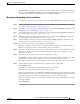
Trouble Isolation
Hardware-related trouble usually means power system failure or connectivity failure. Since testing for
connectivity can uncover power failures, this procedure begins with a connectivity test on each type of
physical link in the Cisco Broadband Local Integrated Services Solution. The following list describes
the three kinds of physical links that connect the solution components:
• IP links that connect all solution components to the Cisco BTS 10200 management IP network.
In addition to network cards and cabling terminating in each component, the management IP
network can also include switches and/or routers.
• SS7 links from the PSTN that terminate in the Cisco BTS 10200.
• Bearer trunks from the PSTN that terminate in the Cisco MGX 8850 Media Gateway.
Each type of link requires different troubleshooting techniques, which are covered in the following
procedure:
Step 1 Test IP connectivity.
Verify that each solution component is connected to the same IP management network. The solution IP
management network allows each component to send and receive messages to and from all the other
components in the solution that are conected to the IP management network.
Use the ping command to verify IP connectivity among all the solution components. In order to do this,
you will need to know the IP address of each solution component. You can attempt to ping each device
from any of the following locations:
• A PC or workstation on the same LAN as the solution components
• When you are logged in to the Cisco BTS 10200 EMS
• When you are logged in to the Cisco Media Gateway (MGW)
If you cannot successfully ping one or more devices, troubleshoot that device to ensure that it is
operating properly.
Step 2 Test SS7 link connectivity.
Signaling messages are received from the SS7 signaling network via SS7 links that terminate in the
Cisco BTS 10200. After verifying that you can successfully ping other devices from the Cisco BTS
10200, use the following command to verify SS7 link connectivity.
CLI> show ss7-cic trunk-id=<id>; tgn-id=<id>; dpc=<num>;
where all of the following tokens are optional
• trunk-id—is the system generated trunk id
• tgn-id—is the user provisioned trunk group id
• dpc—is the destination point code of the STP reached via the specified trunk