CH A P T E R 6 NPE-G2 Overview This chapter describes the NPE-G2 and contains the following sections: Caution • Supported Platforms, page 6-1 • Software Requirements, page 6-2 • NPE-G2 Description and Overview, page 6-2 • NPE-G2 Memory Information and Specifications, page 6-11 • Fiber Optic Cleaning Information, page 6-23 You must copy and save your running configuration file to a CompactFlash Disk, PC Card, or TFTP server before you install the NPE-G2.
Chapter 6 NPE-G2 Overview Software Requirements Software Requirements For minimum software release information, see the “Software Requirements” section on page 8-4. Note The NPE-G2 has its own Cisco IOS software image with the prefix “c7200p-” in the software images filenames, including the boot image. The NPE-G2 does not boot up with a software image with the prefix “c7200-”. Previous network processing engines, or the network services engine, do not boot up with the “c7200p-” boot image.
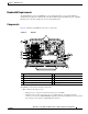
Chapter 6 NPE-G2 Overview NPE-G2 Description and Overview Bandwidth Requirements The Gigabit Ethernet ports on the NPE-G2 do not use bandwidth points, nor does the Fast Ethernet management port. When used with any I/O controller, the Ethernet ports, Fast Ethernet ports, or Gigabit Ethernet ports on the I/O controller also do not use bandwidth points. Components Figure 6-1 illustrates the NPE-G2 and its major components.
Chapter 6 NPE-G2 Overview NPE-G2 Description and Overview • Cache memory The NPE-G2 has two levels of cache: primary and secondary cache that are internal to the microprocessor with secondary unified cache for data and instruction. • The NPE-G2 uses DDR SDRAM for providing code, data, and packet storage. • Two environmental sensors for monitoring the cooling air as it enters and leaves the chassis.
Chapter 6 NPE-G2 Overview NPE-G2 Description and Overview • The port numbering for the interfaces on the NPE-G2 starts with 0/1 and not with 0/0, as is typical for other interface cards. This is to avoid conflicts with the Ethernet and Fast Ethernet ports on an I/O controller, if it is also installed.
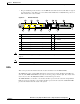
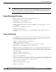
Chapter 6 NPE-G2 Overview NPE-G2 Description and Overview Figure 6-3 NPE-G2 LEDs 1 GIGABI T ETHE RNET 0 LINK ACTV 3 /3 5 FE LINK E AUX FE 0/2 FOR MA NAGE USE ON MENT LY 2 NETWO RK PRO CESSIN G ENGIN COMPA E - G2 CT U S B CONSOL USB 6 FLASH CF ACTV 149063 EN RJ45 SYST STAT PWR OK 4 7 Table 6-1 No.
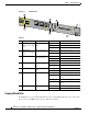
Chapter 6 NPE-G2 Overview NPE-G2 Description and Overview CompactFlash Disks are smaller in size than Type 2 Flash Disks but provide the same Attachment (ATA) interface and equivalent functionality. This interface complies with the ANSI ATA Interface Document X3T13.1153 D Rev. 9 specification. The CompactFlash Disk provides 256 MB of storage space.
Chapter 6 NPE-G2 Overview NPE-G2 Description and Overview To remove a CompactFlash Disk from the CompactFlash Disk slot, complete the following steps: Step 1 Press the ejector button on the slot. (See 3 in Figure 6-4.) Step 2 Grasp the CompactFlash Disk and pull it from the slot. Step 3 Place the CompactFlash Disk in an antistatic bag. Note All CompactFlash Disks must be formatted before their initial use.
Chapter 6 NPE-G2 Overview NPE-G2 Description and Overview Summary of Important NPE-G2 Information Caution The NPE-G2 requires that you copy and save your running configuration file to a CompactFlash Disk, PC Card, or TFTP server before you install the NPE-G2. For instructions on copying and saving your configuration file, see the “Copying the Configuration File” section on page 7-4 in Chapter 7, “NPE-G1 and NPE-G2 Installation and Configuration Information.
Chapter 6 NPE-G2 Overview NPE-G2 Description and Overview Note The Gigabit Ethernet interfaces on the NPE-G2 do not support the Inter-Switch Link (ISL) VLAN encapsulation protocol. We recommend that customers use the IEEE 802.1Q VLAN encapsulation protocol as an alternative. Where an application requires the use of ISL, this can be provided by the Fast Ethernet or Gigabit Ethernet port adapters or I/O controllers.
Chapter 6 NPE-G2 Overview NPE-G2 Memory Information and Specifications • SDRAM—synchronous dynamic random-access memory. • SDRAM-fixed—SDRAM of a fixed size or quantity; can be replaced, but not upgraded. • SFP module—small form-factor pluggable module. • Unified cache—Instruction cache and data cache are combined. For example, a processor may have primary cache with separate instruction and data cache memory, but unified secondary cache. • USB—universal serial bus.
Chapter 6 NPE-G2 Overview NPE-G2 Memory Information and Specifications 2045K bytes of NVRAM. 250603K bytes of USB Flash usbflash0 (Read/Write) 125163K bytes of USB Flash usbflash1 (Read/Write) 250368K bytes of ATA PCMCIA card at slot 2 (Sector size 512 bytes). 65536K bytes of Flash internal SIMM (Sector size 512K). Configuration register is 0x0 Table 6-2 provides memory specifications and Table 6-3 provides user replaceable memory configuration information for the NPE-G2.
Chapter 6 NPE-G2 Overview NPE-G2 Memory Information and Specifications Table 6-5 NPE-G2 USB Flash Memory Module Specifications Token Size Product Number 1 64-MB USB Flash Token for Cisco 1800/2800/3800/7200 MEMUSB-64FT= 12-MB USB Flash Token for Cisco 1800/2800/3800/7200 MEMUSB-128FT= 1. Also known as flash memory modules.
Chapter 6 NPE-G2 Overview NPE-G2 Memory Information and Specifications Table 6-7 Pin RJ-45 Port Pinouts 10/100 Signal 1 Tx Data+ 2 Tx Data– Gigabit Ethernet Signal 1 Tx A+ Tx A– 2 3 Rx Data+ 4 N/C Tx C+ 5 N/C Tx C– 6 Rx Data– Rx B– 7 N/C Rx D+ 8 NC Rx D– Rx B+ 1. Tx Data = Transmit Data 2. Rx Data = Receive Data Note With reference to the RJ-45 pinout in Table 6-7, proper common-mode line terminations should be used for the unused Category 5 UTP cable pairs 4/5 and 7/8.
Chapter 6 NPE-G2 Overview NPE-G2 Memory Information and Specifications Four Twisted-Pair Crossover Cable Schematics for 10/100/1000 and 1000BASET SFP Module Ports 1 2 1 TPO+ 1 TP0+ 2 TPO- 2 TP0- 3 TP1+ 3 TP1+ 6 TP1- 6 TP1- 4 TP2+ 4 TP2+ 5 TP2- 5 TP2- 7 TP3+ 7 TP3+ 8 TP3- 8 TP3- 2 Router Figure 6-8 Hub Ethernet/Fast Ethernet Straight-Through and Crossover Cable Pinouts 1 2 3 4 3 5 1 TxD+ 2 TxD– 1 RxD+ 2 RxD– 1 TxD+ 2 TxD– 1 TxD+ 2 TxD– 3 RxD+ 6 RxD– 3 TxD+ 6 TxD– 3 RxD+
Chapter 6 NPE-G2 Overview NPE-G2 Memory Information and Specifications Gigabit Ethernet SFP Connection Equipment The small for-factor pluggable (SFP) port is a 1000-Mbps optical interface in the form of an LC-type duplex port that supports IEEE 802.3z interfaces compliant with the 1000BASEX standard. (See Figure 6-10.) Note Warning The SFP module you ordered is shipped installed in the NPE-G2.
Chapter 6 NPE-G2 Overview NPE-G2 Memory Information and Specifications Table 6-8 provides SFP module specifications. Table 6-8 SFP Module Specifications Specification Description Dimensions (H x W x D) Height: 0.33 in. (8.5 mm) Depth: 0.53 in. (13.4 mm) Width: 2.22 in. (56.5 mm) Connectors Multimode fiber-optic: LC Single-mode fiber-optic: LC The NPE-G2 supports single Gigabit Ethernet interfaces based on SFP technology.
Chapter 6 NPE-G2 Overview NPE-G2 Memory Information and Specifications Table 6-9 provides SFP port cabling specifications. Table 6-9 SFP Port Cabling Specifications Wavelength (nm) SFP Module Fiber Type Core Size (microns) Modal Bandwidth (MHz/km) Cable Distance 100BASE-FX SFP-GE-F= 1270 1300 1380 MMF 62.5 2.5 50.0 50.0 500 6562 ft (2 km) 1000BASE-LX/LH SFP-GE-L= 1300 MMF1 62.5 50.0 50.0 9/10 500 400 500 — 1804 ft (550 m) 1804 ft (550 m) 1804 ft (550 m) 6.
Chapter 6 NPE-G2 Overview NPE-G2 Memory Information and Specifications Table 6-11 provides CWDM SFP module option information for the NPE-G2.
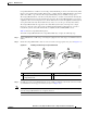
Chapter 6 NPE-G2 Overview NPE-G2 Memory Information and Specifications Figure 6-11 Mode-Conditioning Patch Cord for an SFP Module 4 1 // 2 // Offset 8 TX 3 5 6 7 4 1 Gray color identifier 5 Single-mode fiber 2 To Gigabit Ethernet interface 6 Offset 3 Blue color identifier 7 Beige color identifier 4 Multimode fiber 8 To cable plant 84159 RX 7 // The mode-conditioning patch cord assembly is composed of duplex optical fibers, including a single-mode-to-multimode offset launc
Chapter 6 NPE-G2 Overview NPE-G2 Memory Information and Specifications Note When connecting to an auxiliary port on a Cisco 7200 VXR router, the port will not function at baud rates higher than 19.2k. If the baud rate on the connecting device is set higher than 19.2k, either garbled text or nothing will be displayed on the screen. Refer to Table 6-13 for a list of the pins used on the RJ-45-to-DB-25 adapters, used with an RJ-45 cable, to connect terminals and modems to the Cisco 7200 series routers.
Chapter 6 NPE-G2 Overview NPE-G2 Memory Information and Specifications The Cisco 7200 series routers ship with a roll-over cable. Connection to a terminal or a modem requires an RJ-45-to-DB-25 adapter, and possibly a DB-25-to-DB9 adapter. Refer to Table 6-13 for the cable and adapter configurations that can be used to connect terminals and modems to the Cisco 7200 series routers.
Chapter 6 NPE-G2 Overview Fiber Optic Cleaning Information Table 6-14 Console Port Signals for the NPE-G2 Pin1 Signal Direction Description 1 CTS Out Clear To Send (tracks RTS) 2 DSR Out Data Set Ready (always on) 3 RXD Out Receive Data 4 GND — Signal Ground 6 TXD In Transmit Data 7 DTR In Data Terminal Ready 8 RTS In Ready To Send 1. Any pin not referenced is not connected.
Chapter 6 NPE-G2 Overview Fiber Optic Cleaning Information Network Processing Engine and Network Services Engine Installation and Configuration 6-24 OL-4448-12